Which two statements are correct about EVPN Pure Type-5 routes? (Choose two.)
A. Pure Type-5 routes rely on Type-7 sync routes
B. Pure Type-5 routes require an overlay next hop.
C. Pure Type-5 routes are also known as IP-VRF-to-IP-VRF.
D. Pure Type-5 routes are advertised with the MAC extended community.
Explanation:
C. Pure Type-5 routes are also known as IP-VRF-to-IP-VRF.
This is the foundational concept behind pure Type-5 routes. Because these routes carry all necessary forwarding information and do not rely on an overlay next-hop or a supporting Type-2 route, they enable direct Layer 3 communication between VRFs (Virtual Routing and Forwarding instances) across different data centers. This model is formally defined in IETF RFC 9136 and is referred to as the "IP-VRF-to-IP-VRF" or "interface-less IP-VRF-to-IP-VRF" model .
D. Pure Type-5 routes are advertised with the MAC extended community.
The key distinction of a pure Type-5 route is that it includes a Router's MAC Extended Community. This BGP extended community carries the MAC address of the advertising switch (VTEP - VXLAN Tunnel Endpoint). It serves a critical role: it provides the necessary next-hop reachability information for the IP prefix, removing the need for a separate overlay next-hop or a recursive route lookup .
Why A and B are incorrect:
A. Pure Type-5 routes rely on Type-7 sync routes.
This statement is false. Type-7 routes are not a standard EVPN route type used in this context. The standard EVPN route types include Type-2 (MAC/IP Advertisement), Type-3 (Inclusive Multicast), Type-4 (Ethernet Segment), and Type-5 (IP Prefix). Pure Type-5 routes are specifically designed to avoid relying on other route types, not to depend on a non-existent Type-7 .
B. Pure Type-5 routes require an overlay next hop.
This statement is the opposite of the truth. The entire purpose of a "pure" Type-5 route is to NOT require an overlay next-hop. In the standard (or non-pure) Type-5 route model, a gateway IP address is required as an overlay next-hop, which in turn depends on a Type-2 route for recursive resolution. A pure Type-5 route removes this dependency by embedding the next-hop information directly within the route via the Router's MAC Extended Community .
Reference
Juniper Networks Documentation: Confirms pure Type-5 routes are for IP-VRF-to-IP-VRF and are advertised with a router MAC extended community, requiring no overlay next-hop or Type-2 route .
IETF RFC 9136: Defines the "interface-less IP-VRF-to-IP-VRF model" that underlies pure Type-5 route operation
You want to validate a recursive lookup for an EVPN route designation. Which route table query will accomplish this task?
A. inet.2
B. default-switch.evpn.0
C. inet.3
D. vxlan.inet.
Explanation:
The inet.2 table is Junos’ dedicated utility routing table for recursive next-hop resolution. When a route (e.g., an EVPN Type‑5 prefix) has a next‑hop address that requires further lookup—such as an overlay gateway IP that must be resolved to a directly connected interface or tunnel endpoint—Junos performs that recursive lookup in inet.2. Querying inet.2 (via show route table inet.2) allows you to validate whether the recursive chain is complete and reachable.
Why the other options are incorrect:
B. default-switch.evpn.0 – Stores EVPN MAC/IP routes (Type‑2, Type‑3, Type‑5) for the default switching instance, used for forwarding decisions, not recursive next‑hop resolution.
C. inet.3 – Holds MPLS label-switched path (LSP) next hops; used for MPLS tunnel resolution (e.g., RSVP, LDP), not for generic recursive lookups in EVPN.
D. vxlan.inet – Not a valid Juniper routing table. VXLAN next‑hop information resides in tables like evpn.0, mpls.0, or is resolved via inet.2.
References:
Juniper TechLibrary: “Routing Tables – inet.2 table is used for recursive next‑hop resolution”
“Junos Routing Fundamentals” – recursive lookups use utility tables like inet.2
Click the Exhibit button.
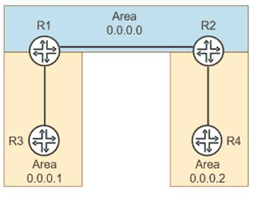
You are troubleshooting suboptimal routing in an enterprise OSPFv2 deployment:
-- R1 is an ABR between Area 0 and Area 1.
-- R2 is an ABR between Area 0 and Area 2.V
-- R3 in Area 1 advertises a network that should be reachable by routers in Area 2.
-- The ABRs are connected in the backbone (Area 0).
On router R2, the show ospf database does not display router LSAs or network LSAs from
Area 1, but an interarea route to R3’s network exists in the routing table. R2 does not have
Type-1 or Type-2 LSAs from Area 1 in its OSPF database.
Referring to the exhibit, which statement is correct?
A. R2 is filtering them using the OSPF import policy.
B. Junos disables Type-1 and Type-2 LSAs by default in Interarea LSDBs.
C. R2 is running OSPFv3, which does not use Type-1 or Type-2 LSAs.
D. Type-1 and Type-2 LSAs are summarized into Type-3 LSAs by ABRs and do not cross area boundaries.
Explanation:
In OSPFv2, Type‑1 (router LSA) and Type‑2 (network LSA) are area‑scoped—they never leave the area in which they originate. When an ABR (like R2) connects Area 0 to Area 2, it does not forward Type‑1 or Type‑2 LSAs from Area 1 into Area 0 or Area 2. Instead, the ABR (R1) in Area 1 summarizes those intra‑area routes into Type‑3 (summary LSA) and floods them into the backbone Area 0. R2 receives those Type‑3 LSAs from Area 0 and installs them as inter‑area routes. This explains why R2 has an inter‑area route to R3’s network but has no Type‑1/Type‑2 LSAs from Area 1 in its database.
Why other options are incorrect:
A. R2 filtering via import policy
– Possible in principle, but the question describes standard OSPF behavior, not a configured filter. No evidence of policy exists.
B. Junos disables Type‑1/Type‑2 LSAs by default
– False. Junos follows standard OSPF; Type‑1/Type‑2 never cross areas by protocol design, not by a disable feature.
C. R2 running OSPFv3
– The question states OSPFv2 deployment. OSPFv3 also does not flood Type‑1/Type‑2 across areas, so this would not explain the symptom.
References:
RFC 2328 (OSPFv2) – Section 3.3: Type‑1 and Type‑2 LSAs are flooded only within their originating area.
Juniper TechLibrary: OSPF Area Types – “ABRs convert intra‑area routes to Type‑3 LSAs for other areas.”
Exhibit
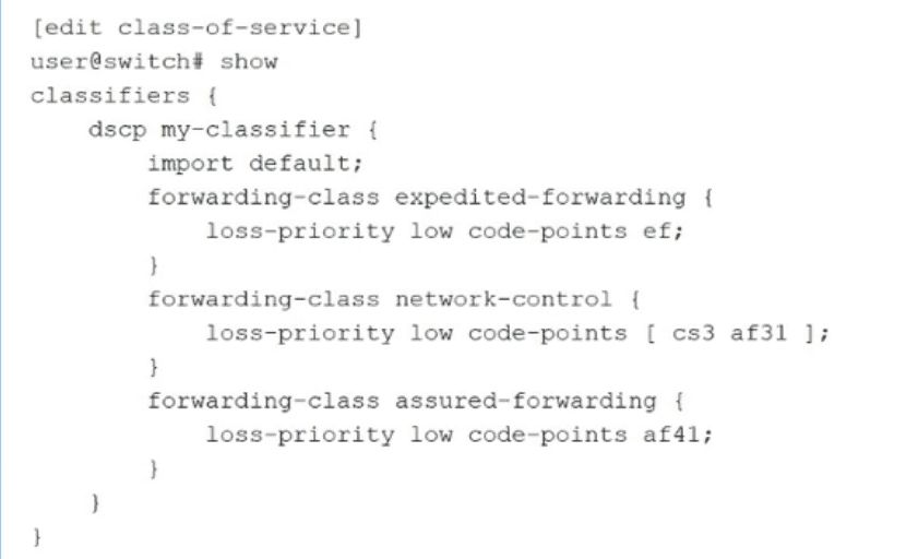
As shown in the exhibit, you have implemented CoS classifiers using Differentiated
Services Code Point (DSCP)
In this scenario, which two statements are correct? (Choose two.)
A. This custom DSCP classifier must be associated with logical interfaces.
B. This custom DSCP classifier must be associated with physical interfaces.
C. The configuration imports all default classification assignments that are not specified.
D. The default classification assignment overwrites all specified classifications
Explanation:
A. This custom DSCP classifier must be associated with logical interfaces.
– Correct. In Junos CoS, after defining a classifier (like my-classifier), you must explicitly associate it with a logical interface using the classifiers statement under [edit class-of-service interfaces
C. The configuration imports all default classification assignments that are not specified.– Correct. The import default; statement in the classifier configuration explicitly imports the system’s default DSCP classification mapping. Any DSCP value not matched by the user‑defined entries will fall back to the default classification (e.g., best‑effort forwarding class). This ensures complete coverage without needing to redefine every possible code point.
Why B and D are incorrect:
B. This custom DSCP classifier must be associated with physical interfaces.
– Incorrect. Junos attaches classifiers to logical interfaces (unit level), not to physical (ge-, xe-) interfaces directly. Physical interfaces may have multiple logical units, each potentially using a different classifier.
D. The default classification assignment overwrites all specified classifications.
– Incorrect. import default does not overwrite user‑specified entries. Instead, it acts as a fallback: user‑defined code points (like ef, cs3, af31, af41) take priority. If a DSCP value matches a user entry, that mapping is used; otherwise, the default classification applies.
References:
Juniper TechLibrary: “Classifiers – Importing the Default Classifier” – import default adds default mappings as a low‑priority fallback.
Juniper TechLibrary: “Applying Classifiers to Logical Interfaces” – Classifiers are configured under interfaces
Exhibit.
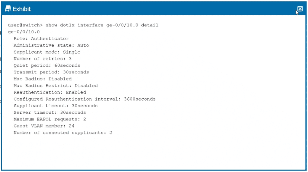
You want to limit port access to only one device at a time.
Referring to the exhibit, which configuration change will accomplish this task?
A. Enable MAC RADIUS restrict.
B. Change the supplicant mode to multiple.
C. Change the supplicant mode to single-secure.
D. Change the maximum EAPOL request to l.
Explanation:
In Junos OS for EX Series switches, the supplicant mode on an 802.1X authenticator interface determines how many devices can connect. To restrict port access to only one device at a time, you must configure single-secure mode.
Per Juniper documentation :
single-secure – Authenticates only one end device to connect to the port. No other device is allowed to connect until the first device logs out. This directly achieves your goal of limiting port access to a single device.
Why other options are incorrect:
A. Enable MAC RADIUS restrict
– This forces the interface to use only MAC RADIUS authentication (bypassing 802.1X) but does not limit the number of connected devices. It controls how authentication happens, not how many devices can access the port .
B. Change the supplicant mode to multiple
– This allows multiple devices to connect to the port, with each device authenticated individually. This is the opposite of limiting to one device .
D. Change the maximum EAPOL request to 1
– This controls how many EAPOL (Extensible Authentication Protocol over LAN) request retransmissions are sent before timing out, not the number of devices allowed on the port.
References:
Juniper TechLibrary – "802.1X Authentication: single-secure supplicant allows only one end device to connect to the port"
Juniper Configuration Guide– supplicant (multiple | single | single-secure)
While deploying class of service on an EX Series switch, what are two aspects of the scheduler? (Choose two.)
A. It defines a buffer size of the queue to which it is assigned.
B. It defines interface rate-limiting.
C. It provides DiffServ code translation.
D. It identifies the priority of the queue to which it is assigned.
Explanation:
In Juniper EX Series switches, a scheduler defines the properties of an output queue. According to Juniper's official documentation, a scheduler configures four key properties of a queue: the amount of interface bandwidth assigned to the queue, the size of the memory buffer allocated for storing packets, the priority of the queue, and the drop profiles associated with the queue.
A. It defines a buffer size of the queue to which it is assigned
– Correct. The buffer-size configuration statement controls the delay buffer bandwidth, which provides packet buffer space to absorb burst traffic. This buffer size can be configured as a percentage of the total buffer, a specific value, or the remaining available buffer.
D. It identifies the priority of the queue to which it is assigned
– Correct. Priority scheduling determines the order in which an output interface transmits traffic from queues, ensuring important traffic receives better access to the outgoing interface. Junos supports multiple priority levels including low (packets transmitted last) and strict-high (packets transmitted first).
Why B and C are incorrect:
B. It defines interface rate-limiting
– Incorrect. Rate-limiting (shaping) is configured separately using the shaping-rate statement, not as a core property of the scheduler itself. While schedulers manage transmission rates, rate-limiting/shaping is a distinct CoS component.
C. It provides DiffServ code translation
– Incorrect. DiffServ code point translation is handled by classifiers (which map code points to forwarding classes) and rewrite rules (which mark outgoing packets), not by schedulers. Schedulers operate on queues after classification and rewriting have occurred.
References:
Juniper TechLibrary – "Understanding CoS Schedulers" – Scheduler properties include buffer size and queue priority
Juniper J-Web Documentation – Scheduler configuration includes buffer size and scheduling priority fields
Which two EVPN types advertise an ESI without advertising a MAC address? (Choose two.)
A. Type1
B. Type 2
C. Type 3
D. Type 4
Explanation:
The question asks which EVPN route types advertise an Ethernet Segment Identifier (ESI) without advertising a MAC address. According to RFC 7432, EVPN defines several route types, each with a specific purpose and set of advertised information.
A. Type 1 (Ethernet Auto-Discovery Route) – Correct.
Type 1 routes are used for network-wide messaging in multi-homing scenarios and carry the ESI in their NLRI. They do not advertise a MAC address—their purpose is to signal Ethernet segment reachability and enable fast convergence . These routes are advertised on a per-ESI and per-EVI basis .
D. Type 4 (Ethernet Segment Route) – Correct.
Type 4 routes are used for automatic discovery of PE devices attached to the same Ethernet segment and for Designated Forwarder (DF) election . The route carries the ESI but contains no MAC address or label information—its purpose is multi-homing coordination, not MAC advertisement .
Why B and C are incorrect:
B. Type 2 (MAC/IP Advertisement Route) – Incorrect.
Type 2 routes are used to advertise MAC addresses (and optionally IP addresses) learned by a PE router . These routes do include a MAC address field (48 bits) and are the primary mechanism for distributing MAC reachability information across the EVPN domain .
C. Type 3 (Inclusive Multicast Ethernet Tag Route – IMET) – Incorrect.
Type 3 routes are used for broadcast, unknown unicast, and multicast (BUM) traffic optimization . These routes do not carry an ESI; they carry route distinguisher, Ethernet tag ID, and IP address information to enable multicast tunnel establishment.
References:
RFC 7432, Sections 5–8 (EVPN route type definitions)
Juniper TechLibrary – EVPN Route Types
IP Infusion – "EVPN Route Types" (Type 1 and Type 4 definitions)
Your existing enterprise network uses OSPFv3 on Juniper devices. You need to extend the networking into a new building, and it needs to be in its own OSPF area. Your team is debating about making the area a stub Which two statements are correct in this scenario? (Choose two.)
A. Stub areas can have an ASBR
B. Stub areas can also be not-so-stubby areas.
C. Stub areas do not support virtual links.
D. Stub areas can be converted into totally stubby areas.
Explanation:
C. Stub areas do not support virtual links.
– Correct. Virtual links allow a non-backbone area to connect to the backbone area through another non-backbone area when a direct physical connection is not available. However, a virtual link cannot traverse a stub area because stub areas do not carry complete routing information and lack the necessary Type-3 summary LSAs to support virtual link establishment .
D. Stub areas can be converted into totally stubby areas.
– Correct. A regular stub area blocks Type-5 external LSAs but still allows Type-3 summary LSAs from other areas. Converting to a totally stubby area further restricts the area by blocking all Type-3 summary LSAs as well, leaving only intra-area routes and a default route. The ABR simply needs the no-summaries parameter configured—no area type change is required .
Why A and B are incorrect
A. Stub areas can have an ASBR
– Incorrect. A stub area, by definition, cannot contain an ASBR (Autonomous System Boundary Router). External routes (Type-5 LSAs) are blocked from entering stub areas, so having an ASBR within a stub area would generate Type-5 LSAs, violating stub area rules. For external route injection into a stub-like area, you must use an NSSA (Not-So-Stubby Area), which uses Type-7 LSAs .
B. Stub areas can also be not-so-stubby areas
– Incorrect. An area cannot be both a stub area and an NSSA simultaneously—these are mutually exclusive configurations. The two area types serve different purposes: stub areas block all external routes, while NSSAs allow controlled external route injection via Type-7 LSAs .
References
Juniper TechLibrary – OSPF Stub Areas, Totally Stubby Areas, and NSSA configuration guides
RFC 2328 (OSPFv2) – Stub area definitions and restrictions
HPE OSPFv3 documentation – Stub area virtual link limitations
Your Layer 2 network uses 802.1X to authenticate user devices connecting to the network. You are asked to include a new Layer 2 interface connection from the conference room in your network. You must ensure that only a single device is allowed to authenticate on this port at one time to avoid users from being able to plug in a rogue switch to this port. In this scenario, which 802.1X method would you use for the new interface?
A. single-secure supplicant mode
B. multiple supplicant mode
C. single supplicant mode
D. MAC-RADIUS
Explanation:
To restrict a port so that only one device is allowed to authenticate at a time, you must use the single-secure supplicant mode. This mode authenticates the first end device that attempts to connect and then prevents any additional devices from authenticating on that port—even if they provide valid credentials—unless the first device logs out.
This directly addresses the requirement to prevent users from plugging in a rogue switch (which would appear as multiple devices behind a single port).
Why other options are incorrect
B. multiple supplicant mode
– Incorrect. This mode allows multiple devices to authenticate simultaneously on the same port. Each device is individually authenticated, but this would defeat the security requirement because a rogue switch could be connected and multiple devices behind it would all be authenticated.
C. single supplicant mode
– Incorrect. This mode authenticates only one device as well, but unlike single-secure, it does not block additional devices. Instead, if a second device is detected, the switch shuts down the port or forces re-authentication of the first device—depending on configuration. More importantly, single-secure is the Juniper-recommended method for explicitly limiting to exactly one authenticated client at a time.
D. MAC-RADIUS
– Incorrect. MAC-RADIUS bypasses 802.1X and uses only the device's MAC address for authentication. While you can still limit the number of MAC-authenticated devices, the standard method for preventing multiple devices on a single port with 802.1X is the single-secure supplicant mode, not MAC-RADIUS alone.
References:
Juniper TechLibrary – "802.1X Authentication – Single-Secure Supplicant Mode"
JNCIP-ENT Study Guide – Port Authentication (802.1X) Policies
Juniper EX Series Configuration Guide – Access Control and Authentication
Which two statements are correct about EVPN/VXLAN deployments? (Choose two.)
A. VNIs are used for encapsulating and de-encapsulating traffic entering and leaving the tunnels
B. VTEPs are used for encapsulating and de-encapsulating traffic entering and leaving the tunnels.
C. VTEPs are used to identify broadcast domains within an EVPN/VXLAN environment.
D. VNIs are used to identify broadcast domains within an EVPN/VXLAN environment.
Explanation:
B. VTEPs are used for encapsulating and de-encapsulating traffic entering and leaving the tunnels.
– Correct. A VTEP (VXLAN Tunnel Endpoint) is the device that performs the encapsulation and decapsulation of VXLAN frames. When a frame enters a VXLAN tunnel, the source VTEP wraps the original Ethernet frame with a VXLAN header, UDP header, and outer IP header. When the frame exits the tunnel, the destination VTEP removes these headers and forwards the original Ethernet frame to the destination host.
D. VNIs are used to identify broadcast domains within an EVPN/VXLAN environment.
– Correct. A VNI (VXLAN Network Identifier) is a 24-bit identifier included in the VXLAN header that uniquely identifies a Layer 2 broadcast domain or segment. Each VNI corresponds to a virtual network, allowing up to 16 million unique segments. This enables the separation of traffic from different tenants or different VLANs within the same physical infrastructure.
Why A and C are incorrect
A. VNIs are used for encapsulating and de-encapsulating traffic entering and leaving the tunnels.
– Incorrect. VNIs are identifiers carried inside the VXLAN header, but they do not perform the encapsulation/de-encapsulation action. That action is performed by VTEPs. Think of the VNI as a tag, while the VTEP is the device that reads and writes that tag.
C. VTEPs are used to identify broadcast domains within an EVPN/VXLAN environment.
– Incorrect. VTEPs are the tunnel endpoints; they do not serve as identifiers for broadcast domains. Broadcast domains are identified by VNIs. While a VTEP may be configured with multiple VNIs, the VTEP itself is not an identifier.
References:
RFC 7348 – VXLAN architecture (VTEP and VNI definitions)
Juniper TechLibrary – EVPN/VXLAN overview
JNCIP-ENT Study Guide – VXLAN component role
Exhibit
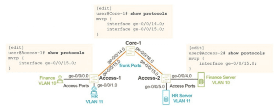
You configured MVRP in your Layer 2 network using the configuration shown in the exhibit.
You verified that the appropnate VLANs are configured and applied on the two access
switches. You are using RSTP as your loop prevention mechanism. Unfortunately, the
users are not able to communicate with their corresponding server attached to the Access-
2 switch.
In this scenario, what should you do to solve this problem?
A. Configure VSTP instead of RSTP as your loop-prevention mechanism.
B. Configure the access interfaces on the Access-2 switch under MVRP.
C. Configure the ge-070716.0 interface on the Core-1 switch under MVRP.
D. Configure the access interfaces on the Access-1 switch under MVRP.
Explanation:
MVRP (Multiple VLAN Registration Protocol) dynamically propagates VLAN registration information across trunk ports. In the exhibit:
Access‑1 has VLAN 10 (Finance) and VLAN 11 (HR) configured on its access ports, and MVRP enabled on trunk interface ge-0/0/15.0 (toward Core‑1).
Access‑2 has VLAN 10 (Finance Server) and VLAN 11 (HR Server) configured, and MVRP enabled on trunk interface ge-0/0/15.0 (toward Core‑1).
Core‑1 has MVRP enabled on ge-0/0/15.0 (toward Access‑1) and also needs MVRP enabled on ge-0/0/14.0 to allow the VLAN declarations from Access‑1 to propagate to Access‑2.
Without MVRP on ge-0/0/14.0 on Core‑1, the VLAN registration information from Access‑1 does not reach Access‑2. The users on Access‑1 cannot communicate with their servers on Access‑2 because the trunk segments are not dynamically propagating the VLAN membership across the entire path.
Why other options are incorrect
A. Configure VSTP instead of RSTP
– Incorrect. The problem is not related to STP type. VSTP (VLAN Spanning Tree Protocol) is used for per‑VLAN STP in mixed‑vendor environments, but RSTP works fine here. The issue is MVRP propagation, not loop prevention.
B. Configure the access interfaces on Access‑2 under MVRP
– Incorrect. MVRP is only needed on trunk ports to propagate VLAN registrations. Access ports (where end hosts connect) do not need MVRP because they are statically assigned to VLANs.
D. Configure the access interfaces on Access‑1 under MVRP
– Incorrect. Access ports on Access‑1 (e.g., ge-0/0/0.0 for Finance, ge-0/0/1.0 for HR) do not need MVRP. Their VLAN membership is statically configured, and they do not propagate VLAN registrations further.
References:
Juniper TechLibrary – MVRP configuration: MVRP must be enabled on all trunk interfaces in the propagation path
JNCIP‑ENT study guide – VLAN registration protocols (MVRP)
You are troubleshooting a multicast deployment in a network. Some multicast groups
operate in PIM-ASM mode and others operate in PIM-SSM mode. While troubleshooting,
you note the following:
- The network uses IGMPv2 for some segments and IGMPv3 for others.
- For group 232.1.1.1, receivers know the exact source IP of the multicast sender
- For group 239.10.10.10. receivers do not know the source address in advance.
Which two statements correctly describe the operational differences between these two
modes in Junos OS? (Choose two.)
A. PIM-ASM supports multiple active sources for a group without requiring receivers to know them in advance, whereas PIM-SSM requires explicit source knowledge
B. In PIM-ASM. the DR first sends a PIM register message to the RP before switching to the shortest-path tree.
C. PIM-SSM requires an RP for initial joins, whereas PIM-ASM can operate without one.
D. PIM-SSM relies on IGMPv3 to signal both the source and the group in the join message, bypassing the RP entirely.
Explanation:
A. PIM-ASM supports multiple active sources for a group without requiring receivers to know them in advance, whereas PIM-SSM requires explicit source knowledge.
– Correct. Any-Source Multicast (ASM) allows any source to send to a multicast group, and receivers join the group without knowing the source IP in advance. Source-Specific Multicast (SSM) requires receivers to know both the source IP and the group IP at join time, typically signaled via IGMPv3's INCLUDE mode, which specifies (S,G) instead of just (*,G).
D. PIM-SSM relies on IGMPv3 to signal both the source and the group in the join message, bypassing the RP entirely.
– Correct. SSM uses IGMPv3's capability to report (S,G) membership. When the receiver's DR receives this, it sends a PIM (S,G) join directly toward the source (without ever involving an RP). This eliminates the need for an RP, shared tree, or register process. In contrast, ASM typically uses IGMPv1/v2 (or IGMPv3 in EXCLUDE mode), which only signals (*,G), requiring RP-based shared trees initially.
Why B and C are incorrect
B. In PIM-ASM, the DR first sends a PIM register message to the RP before switching to the shortest-path tree.
– Incorrect as a difference between ASM and SSM. This describes PIM-ASM behavior accurately, but the question asks for operational differences between the two modes. This statement is true only for ASM, but SSM never uses an RP or register messages at all. However, the wording of the question expects contrasting statements about both modes. Since SSM has no RP, this does not correctly describe a difference of the same type for both modes — and more importantly, this is a description of ASM only, not a valid paired difference.
C. PIM-SSM requires an RP for initial joins, whereas PIM-ASM can operate without one.
– Incorrect. This is backwards. PIM-ASM requires an RP for initial joins (via shared tree), while PIM-SSM does not require an RP at all because joins are sent directly toward the source using (S,G) state.
References
Juniper TechLibrary – PIM-SSM overview: "SSM uses IGMPv3 to join (S,G) directly without an RP"
Juniper TechLibrary – PIM-ASM overview: "ASM uses an RP for shared tree and register process"
| Page 1 out of 6 Pages |
| 12 |
Real-World Scenario Mastery: Our JN0-650 practice exam don't just test definitions. They present you with the same complex, scenario-based problems you'll encounter on the actual exam.
Strategic Weakness Identification: Each practice session reveals exactly where you stand. Discover which domains need more attention, before Enterprise Routing and Switching - Professional (JNCIP-ENT) exam day arrives.
Confidence Through Familiarity: There's no substitute for knowing what to expect. When you've worked through our comprehensive JN0-650 practice exam questions pool covering all topics, the real exam feels like just another practice session.
Copyright © All Rights Reserved