You are using Juniper Apstra to create your DC fabric. The fabric requires the use of
configlets and requires a property set, which you call “test.” While creating the property set,
you encounter an error message.
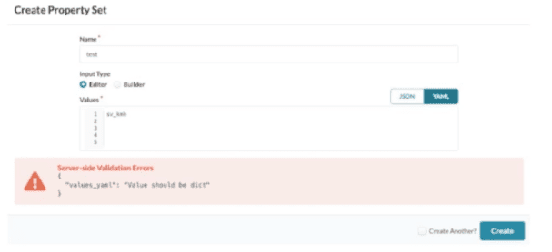
Referring to the exhibit, how would you correct the error?
A. Use the Builder option for input type of YAML.
B. Remove the trailing blank lines.
C. Change to JSON and click Create.
D. Use valid YAML syntax of key: value.
Explanation:
Why D is correct:
Juniper Apstra Property Sets must store data as dictionaries (key: value pairs). The error "Value should be dict" appears because the input 1, 2, 3, 4, 5 is a list, not a dictionary. Changing to YAML syntax like vlans: [1,2,3,4,5] or ids: 1,2,3,4,5 provides the required key‑value structure.
Why other options are incorrect:
A (Builder option for YAML): The Builder UI doesn’t change data type rules; you still need a dictionary, not a list.
B (Remove trailing blank lines): Blank lines don’t cause the dict error; trailing spaces are ignored by YAML/JSON parsers and are unrelated to dictionary validation.
C (Change to JSON and click Create): JSON alone doesn’t fix the problem – the value must be a JSON object {"key": value}, not an array [1,2,3,4,5].
Reference:
Juniper TechLibrary – Apstra Property Sets:“A property set is a collection of key‑value pairs ... Values can be defined in YAML or JSON dictionary format.” (See “Create a Property Set” in Apstra User Guide.)
What is the purpose of a Juniper Apstra rack?
A. It stores information on how pods connect to super spines.
B. It stores information on how leaf nodes connect to generic devices
C. It stores IP address and ASN pool information.
D. It stores device port data rates and vendor information.
Explanation:
Why B is correct:
In Juniper Apstra, a Rack Type is a modular, reusable definition of the physical structure within a data center rack. Its primary function is to model the internal connectivity between top-of-rack (leaf) switches and the end devices (generic systems) within that specific rack. This includes defining the number of leaf switches, the number of generic systems (servers), and the link speeds,of their connections. By encapsulating this access-layer topology, a rack type becomes a building block that can be repeatedly deployed to scale the fabric quickly.
Why other options are incorrect:
A (Stores pod-to-super-spine connections): This is the function of a "Template," not a Rack. A template defines how multiple racks (forming a pod) connect to spine or super-spine nodes.
C (Stores IP address and ASN pool information): This is handled by the "Resources" feature in Apstra, which manages pools for IP addresses, AS numbers, and VNIs.
D (Stores device port data rates and vendor information) This is defined in "Logical Devices." Logical devices represent switch hardware without specifying the vendor.
Reference:
Juniper Apstra Documentation: "A rack type is the combination of generic systems and top-of-rack switches... consists of a Leafs section... and a Generic Systems section" .
You are building a blueprint using Juniper Apstra and must change the cable map to match the physical environment. Where in the blueprint UI is this task accomplished?
A. Active Physical Links
B. Staged Physical Links
C. Active Connectivity Templates
D. Staged Connectivity Templates
Explanation:
Why B is correct:
In Juniper Apstra, all changes to a blueprint are made in the "Staged" state before being committed to the "Active" state. The cable map (cabling map) is modified by navigating to Staged > Physical > Links and clicking the Edit cabling map button. This opens a dialog where you can change interface names, IP addresses, or override Apstra's automatically generated cabling to match physical patch panel connections. After making changes, you click Update, then commit from the Uncommitted tab to activate the new cabling map.
Why other options are incorrect:
A. Active Physical Links — The Active tab displays the currently deployed topology for read‑only viewing. You cannot edit the cable map here; all changes require Staged mode.
C. Active Connectivity Templates — Connectivity Templates define logical connectivity (VLANs, routing policies), not physical cabling between device ports.
D. Staged Connectivity Templates — This manages logical service connectivity (e.g., attaching VLANs to interfaces), not the physical cable map between switches.
Reference:
Juniper TechLibrary: "From the blueprint, navigate to Staged > Physical > Links and click the Edit cabling map button"
Which type of generic system should you select when adding a new server inside an existing rack type?
A. Internal generic
B. Rack generic
C. External generic
D. Embedded generic
Explanation:
When adding a server inside an existing rack type, you select "Internal" as the generic type because the server resides within the rack structure and is part of the data center fabric's access layer. Internal generic systems represent devices—such as servers, storage arrays, or bare-metal hosts—that are physically located inside the rack and connect directly to leaf or access switches .
In Juniper Apstra, internal generic systems are fully documented in the blueprint as part of the rack topology. They are not managed by Apstra (meaning Apstra does not push configurations to them), but their connectivity, port mappings, and link states are modeled to provide complete visibility and automation for attached switch ports . When you add a server within an existing rack type, the generic system is automatically associated with the leaf switches defined in that rack type's topology .
Why other options are incorrect:
B. Rack generic
— This is not a valid Apstra generic system type. Generic systems are classified as "Internal" or "External," not by the term "Rack generic" .
C. External generic
— External generic systems represent devices outside the data center rack structure, such as edge routers, firewalls, or WAN gateways that provide connectivity to external networks. They are not appropriate for servers inside a rack .
D. Embedded generic
— This is not a recognized generic system type in Juniper Apstra. The platform uses only "Internal" and "External" classifications for generic systems .
Reference:
Juniper TechLibrary: "Systems that are not managed by Apstra and that are part of a rack topology are called (internal) generic systems" . See also Apstra Cloudlabs: "In Apstra, servers are represented as Generic Systems... Generic Type: Internal" .
You are asked to deploy a collapsed fabric architecture. Which two statements are correct about this deployment? (Choose two.)
A. All EVPN-VXLAN overlay functions are provided by the leaf devices.
B. Leaf devices are full-mesh connected.
C. Top-of-rack switches are full-mesh connected.
D. Top-of-rack switches provide VXLAN support.
Explanation:
In a collapsed fabric architecture (also known as collapsed spine architecture), the traditional three-stage Clos topology is simplified by collapsing the leaf layer functions onto the spine devices . This means there is no separate leaf layer; instead, the Top-of-Rack (ToR) switches themselves act as the leaf devices. These ToR switches must therefore provide VXLAN support and handle all EVPN-VXLAN overlay functions, including VXLAN tunnel endpoints (VTEPs), IRB interfaces, and MAC/VXLAN route distribution via EVPN control plane .
Why A is correct:
In collapsed fabric, the ToR switches (which serve as the combination spine/leaf) provide all EVPN-VXLAN overlay functions. There are no dedicated leaf switches; the overlay edge exists entirely on the ToR devices .
Why D is correct:
ToR switches in a collapsed fabric must provide VXLAN support because they serve as the VTEPs (VXLAN Tunnel Endpoints) for all overlay traffic entering and leaving the fabric .
Why other options are incorrect:
B. Leaf devices are full-mesh connected.
This is incorrect because in a collapsed fabric, there are no dedicated leaf devices to be full‑mesh connected. The spine devices (ToRs) handle the leaf functions, and they are not typically fully meshed with each other—they are connected via inter‑switch links (ISLs) as a small cluster, not a full mesh .
C. Top-of-rack switches are full-mesh connected.
This is incorrect. In a standard collapsed fabric of two ToR switches, they are connected directly (one inter-switch link) but do not form a full mesh among themselves. Adding more than two collapsed spine switches would not involve a full mesh either; they follow a simple mesh design, not a true full‑mesh fabric .
Reference:
Juniper Documentation: "In collapsed spine architecture, leaf device functions are collapsed onto the spine devices. Because there is no leaf layer, you configure the VTEPS and IRB interfaces on the spine devices, which are at the edge of the overlay network" . "The Collapsed Data Center Fabric with Juniper Apstra JVD uses EVPN-VXLAN for the control plane and eBGP for both underlay and overlay signaling" .
What does clicking the indicated icon shown in the exhibit accomplish?
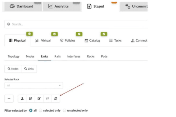
A. It refreshes the screen.
B. It fetches the discovered Link Layer Discovery Protocol (LLDP) data.
C. It erases the entire cable map to start over.
D. It changes the speed of existing links.
Explanation:
In Juniper Apstra, the icon indicated in the exhibit (the fifth button above the links list when viewing Staged > Physical > Links) is the "Fetch discovered LLDP data" button . This button allows you to discover actual physical cabling by having Apstra query LLDP information from the devices already connected and powered on in your network .
Why other options are incorrect:
A. It refreshes the screen.
— Screen refresh is accomplished by browser refresh or standard UI navigation, not by this dedicated LLDP discovery button. The button performs a specific network data collection function, not a generic UI refresh.
C. It erases the entire cable map to start over.
— There is no single-button "erase all" function for the cable map. LLDP discovery compares and optionally updates the map, but does not wipe it entirely. Erasing would be a manual, multi-step process.
D. It changes the speed of existing links.
— Link speeds are configured through interface settings, logical device profiles, or port speed overrides—not through the LLDP fetch operation. LLDP discovers neighbor relationships, not speed configurations.
Reference:
Juniper Networks TechLibrary: "If you've already cabled up your devices, you can have Apstra discover your existing cabling instead of using the cabling map prescribed by Apstra" . "From the blueprint, navigate to Staged > Physical > Links and click the Fetch discovered LLDP data button (fifth of five buttons above links list)" .
When creating a probe, an operator wants to make it easy to view that probe’s output. In this scenario, which element must be created to accomplish this task?
A. A dashboard widget
B. A predefined probe
C. A processor
D. A stage
Explanation:
In Juniper Apstra's Intent-Based Analytics (IBA) system, a probe is a data-processing pipeline that collects telemetry data, applies processing, and generates anomalies when the network deviates from intended states . Once a probe is created and collecting data, the operator needs a way to visualize that output meaningfully. Creating a dashboard widget is the required element to display a probe's output in an easily viewable format . Dashboards allow you to add widgets showing data from custom probes alongside built-in analytics, organizing metrics in ways most meaningful for your operations team .
Why other options are incorrect:
B. A predefined probe
— Predefined probes are pre-configured analytics pipelines that come with Apstra out-of-the-box (such as device traffic probe). While useful, this question scenario involves creating a custom probe, and a predefined probe is a complete probe itself, not an element created to view a probe's output .
C. A processor
— Processors are components inside a probe that perform data analytics functions (grouping, checking, periodic measurements, arithmetic operations) . They inject raw data into the pipeline, perform calculations, and compare results against expected states . Processors enable the probe to function but do not provide a user-viewable output interface.
D. A stage
— In IBA terminology, a stage represents an output port or intermediate data point within a probe's pipeline. When creating a probe via API, stages are defined with names, descriptions, tags, and units to organize output data streams . However, a stage is an internal probe component (part of the analytics pipeline structure), not a user-facing visualization element for viewing the probe's output.
Reference:
Juniper Apstra Documentation:
"Once you've created custom probes, you can visualize their data in customized dashboards: Add widgets showing data from your custom probes alongside built-in analytics" . See also "You can see the data behind the dashboards by clicking on the stage — these probes show how data is collected, analyzed, and alerts can be fully customized" .
You have accessed your deployed blueprint and see the banner shown in the exhibit.

Which two statements are correct in this scenario? (Choose two.)
A. Devices must be assigned to profiles.
B. There are changes that are not active on the fabric.
C. Resources must be assigned to devices.
D. There are anomalies that must be addressed.
Explanation:
Why B is correct:
In Apstra, blueprint modifications are made in a "Staged" state. A banner appears when staged changes exist but have not been committed. Until committed, the active fabric does not reflect these changes.
Why D is correct:
Apstra continuously validates intent. If the live network deviates from the blueprint (e.g., link down, BGP session down, mismatched VLANs), an anomalies banner appears, indicating needed remediation.
Why A and C are incorrect:
A (Devices must be assigned to profiles) – Device profiles are assigned during initial design, not typically shown as a post‑deployment banner warning.
C (Resources must be assigned to devices) – Resource pools (IPs, ASNs) are allocated during blueprint creation, not as a runtime banner after deployment.
Reference:
Juniper TechLibrary – Apstra Blueprint Banner Messages: "Uncommitted changes exist" and "Anomalies detected in the fabric" are standard banner states requiring user action.
You are trying to deploy a five-stage template to a blueprint as shown in the exhibit. You
cannot see your template name in the list of available templates.
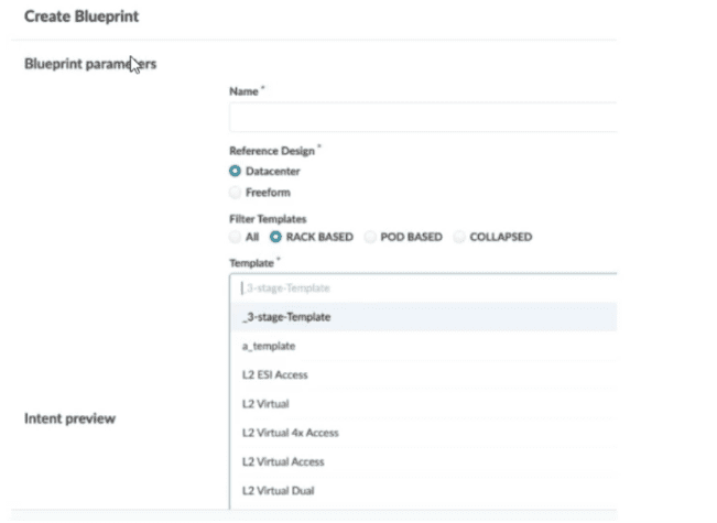
In this scenario, which statement is correct?
A. The Collapsed option should be selected.
B. You must include “five-stage” in the template name for it to appear in the list.
C. The Pod Based option should be selected.
D. Only Freeform-type blueprints support five-stage templates.
Explanation:
In Juniper Apstra, the template type determines the fabric architecture you are building. When creating a blueprint, the available templates are filtered based on the Reference Design and the Filter Templates options selected .
Why other options are incorrect:
A. The Collapsed option should be selected.
— The Collapsed filter is used for collapsed fabric architectures (spineless designs), not for five-stage fabrics . Selecting this would still not display your pod-based five-stage template.
B. You must include "five-stage" in the template name for it to appear in the list.
— Template names in Apstra are user-defined strings . There is no keyword requirement such as "five-stage" for a template to be listed. The filtering mechanism is based on the template type setting (Rack Based, Pod Based, or Collapsed), not on name matching.
D. Only Freeform-type blueprints support five-stage templates.
— This is incorrect. The Datacenter reference design fully supports five-stage fabrics using pod-based templates . Freeform blueprints are used for non-standard designs or heterogeneous environments and are not required for standard five-stage Clos deployments.
Reference:
Juniper Networks Documentation
— *"Pod-based templates are for designing a 5-stage fabric (that is, linking multiple rack-based templates to a superspine)"* ; "From the left navigation menu, navigate to Design > Templates and click Create Template... select POD BASED" ;
What are two available Juniper Apstra template types? (Choose two.)
A. Collapsed
B. Rack-based
C. Compressed
D. Device-based
Explanation:
In Juniper Apstra, templates are the architectural blueprints that define how network devices interconnect to form a data center fabric. The platform provides three distinct template types — rack-based, pod-based, and collapsed — each designed for a specific fabric architecture .
B.Rack-based templates are used for designing 3-stage Clos fabrics (leaf-spine architecture within a single pod). They define the type and number of racks to connect as top-of-rack switches, specifying the number of spines, link speeds between spine and leaf nodes, ASN assignment methods, and overlay control protocols .
A. Collapsed templates (also called spineless templates) allow you to consolidate leaf, border leaf, and spine functions into a single pair of devices. In this architecture, a full mesh topology is created at the leaf level instead of at leaf-spine connections. These templates have specific limitations, including no support for IPv6, no mixing of vendors inside redundant leaf devices, and leaf-to-leaf links limited to full mesh .
Why other options are incorrect:
C. Compressed — This is not a valid Juniper Apstra template type. No official Juniper documentation references a "compressed" template type .
D. Device-based — This is not a recognized template type in Juniper Apstra. While logical devices and device profiles exist within the platform's design hierarchy, "device-based" is not a template classification .
Reference:
Juniper Networks TechLibrary — "Templates can be rack-based, pod-based, or spineless (collapsed)" ; See also "Rack-based templates... Collapsed templates... Pod-based templates" .
Which two statements are correct about a Juniper Apstra server? (Choose two.)
A. The Juniper Apstra server uses Layer 2 to communicate with managed devices.
B. The Juniper Apstra server requires one network adapter connection for each managed device.
C. The Juniper Apstra server uses Layer 3 to communicate with managed devices.
D. The Juniper Apstra server requires a single network adapter.
Explanation:
Why C is correct:
The Juniper Apstra server communicates with managed devices using IP-based (Layer 3) connectivity. The official documentation states that "TCP connectivity is the only requirement between nodes" and that "there is no strict latency requirement or a requirement for Layer 2 (L2) connectivity between the server and the devices you are going to manage – it will be all IP-routed packets from the Juniper Apstra server to the management ports of the devices" . This design allows Apstra to manage devices across routed management networks without needing direct Layer 2 adjacency.
Why D is correct:
The Juniper Apstra server requires only a single network adapter for operation. Official Juniper documentation lists the network requirement as "1 network adapter, initially configured with DHCP" . Apstra does not need multiple network interfaces to communicate with managed devices, as all management traffic uses the single adapter.
Why other options are incorrect:
A. The Juniper Apstra server uses Layer 2 to communicate with managed devices.
This is incorrect. Apstra explicitly does not require Layer 2 connectivity; it uses IP routing (Layer 3) between the server and device management ports .
B. The Juniper Apstra server requires one network adapter connection for each managed device.
This is incorrect. A single network adapter is sufficient regardless of how many devices Apstra manages. The server communicates with all managed devices through the same network interface .
Reference:
Juniper Networks TechLibrary:"TCP connectivity is the only requirement between nodes" and "Apstra server and all the Apstra agents act as a distributed operating system"
You are creating a new security policy using Juniper Apstra.
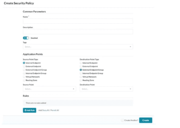
Referring to the exhibit, which application point should you select to allow or deny traffic to
or from a particular VRF?
A. Routing Zone
B. External Endpoint
C. Internal Endpoint
D. Virtual Network
Explanation:
In Juniper Apstra, a Routing Zone (RZ) directly aligns with a Virtual Routing and Forwarding (VRF) instance . VRFs provide isolation at the routing table level, separating tenants so they cannot reach each other at Layer 3. If you want to allow or deny traffic to or from an entire VRF, you must select the Routing Zone as the application point in your security policy.
The Juniper Apstra documentation explicitly states: "Routing Zones (RZ) are the highest-level objects. RZ is directly aligned with a Virtual Routing and Forwarding instance (VRF)" . When creating security policies, the source or destination object can be selected from Routing Zones (all Virtual Networks within an SZ) . This means selecting a Routing Zone applies the policy to all Virtual Networks contained within that VRF, effectively controlling traffic to or from a particular VRF as a whole.
Why other options are incorrect:
B. External Endpoint
— External endpoints represent IP ranges or subnets outside the Apstra blueprint . These are used for traffic flowing between the fabric and external networks (e.g., WAN gateways, firewalls), not for applying policy to an entire VRF.
C. Internal Endpoint
— Internal endpoints are specific IP addresses (typically /32) associated with Virtual Networks inside the blueprint . These are granular objects for host-level policies, not for controlling all traffic within an entire VRF.
D. Virtual Network
— A Virtual Network represents a single L2/L3 segment (VXLAN or VLAN). Selecting a Virtual Network applies policy only to that specific network, not to all networks within the VRF . To cover an entire VRF (multiple Virtual Networks), you must select the Routing Zone instead.
Reference:
Juniper Networks TechLibrary — "Security Policies: Routing Zones (RZ) are the highest-level objects. RZ is directly aligned with a Virtual Routing and Forwarding instance (VRF)."
Juniper Networks TechLibrary — "Security policies allow or block traffic between endpoints based on their IP addresses, port numbers, and protocols... Routing Zone (RZ) which are rendered as Virtual Routing and Forwarding (VRF) instances on physical devices."
| Page 1 out of 6 Pages |
| 12 |
Real-World Scenario Mastery: Our JN0-481 practice exam don't just test definitions. They present you with the same complex, scenario-based problems you'll encounter on the actual exam.
Strategic Weakness Identification: Each practice session reveals exactly where you stand. Discover which domains need more attention, before Data Center - Specialist (JNCIS-DC) exam day arrives.
Confidence Through Familiarity: There's no substitute for knowing what to expect. When you've worked through our comprehensive JN0-481 practice exam questions pool covering all topics, the real exam feels like just another practice session.
Copyright © All Rights Reserved