What is the maximum allowable MTU size for a default GRE tunnel without IPv4 traffic fragmentation?
A. 1496 bytes
B. 1480 bytes
C. 1500 bytes
D. 1476 bytes
Explanation:
A default GRE tunnel adds 24 bytes of encapsulation overhead: a 20‑byte outer IPv4 header plus a 4‑byte GRE header. The physical Ethernet interface has a default maximum transmission unit (MTU) of 1500 bytes. To prevent fragmentation of IPv4 traffic inside the tunnel — which would occur if the tunnel MTU plus overhead exceeded 1500 bytes — the tunnel interface MTU must be set to 1500 minus 24 = 1476 bytes. At this value, the router encapsulates a 1476‑byte inner packet into a 1500‑byte outer frame, fitting perfectly within the physical MTU. No fragmentation occurs, and the DF bit (Don't Fragment) is respected.
Why other options are wrong:
A. 1496 bytes
– This subtracts only 4 bytes (GRE header) but ignores the 20‑byte outer IP header. Encapsulating a 1496‑byte packet produces a 1520‑byte frame (1496 + 24), exceeding 1500 bytes. This causes fragmentation or packet drops if the DF bit is set.
B. 1480 bytes
– This subtracts 20 bytes (outer IP header) but omits the GRE header. The resulting encapsulated packet would be 1480 + 24 = 1504 bytes, still above the 1500‑byte limit, leading to fragmentation.
C. 1500 bytes
– This is the physical Ethernet MTU, not the tunnel MTU. A tunnel MTU of 1500 would produce 1524‑byte frames after adding the 24‑byte GRE/IP header, guaranteeing fragmentation or drops. This is the most common mistake.
References:
Juniper TechLibrary: “GRE Tunneling Overview” – “A GRE tunnel adds 24 bytes of IP + GRE header overhead. To avoid fragmentation, reduce the tunnel MTU by 24 bytes from the physical interface MTU.”
JNCIS‑ENT Study Guide (Tunnels chapter) – “Default Ethernet MTU is 1500 bytes; GRE overhead is 24 bytes; maximum tunnel MTU without fragmentation = 1476 bytes.”
Exhibit:
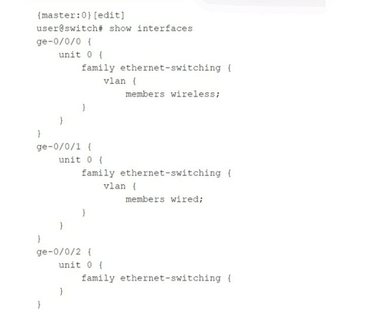
Which statement is correct about the configuration shown in the exhibit?
A. The configuration will not complete the commit check process and will error out.
B. The ge-0/0/0 and ge-0/0/1 interfaces are operating in trunk mode.
C. All three interfaces are operating in access mode.
D. The ge-0/0/2 interface is operating as a Layer 3 interface.
Explanation:
On Juniper EX Series switches, when you configure a family ethernet-switching interface with a specific VLAN membership using the vlan statement and the members keyword, the interface defaults to trunk mode if a VLAN name is explicitly listed. The configuration shown for ge-0/0/0 and ge-0/0/1 specifies members wireless and members wired, respectively, without specifying access or trunk explicitly. In Junos, this implicit syntax creates a trunk port that carries only the specified VLAN (as a tagged member unless native-vlan-id is also set). Both interfaces are therefore operating in trunk mode, carrying their respective VLANs.
Why other options are wrong:
A. The configuration will not complete the commit check process and will error out.
Incorrect. The configuration is perfectly valid and will commit successfully. Juniper switches allow trunk ports with a single VLAN member; this is a common way to limit a trunk to only one VLAN. No commit error occurs.
C. All three interfaces are operating in access mode.
Incorrect. Access mode is configured using the interface-mode access statement under ethernet-switching-options or explicitly on the interface. Here, ge-0/0/0 and ge-0/0/1 use the vlan { members
D. The ge-0/0/2 interface is operating as a Layer 3 interface.
Incorrect. ge-0/0/2 has family ethernet-switching {} with no further configuration. This enables it as a Layer 2 switch port, not a Layer 3 interface. A Layer 3 interface would require family inet with an IP address. The empty ethernet-switching family means the port is a basic Layer 2 port, inheriting default VLAN behavior (typically access VLAN 1 after configuration).
Reference:
Juniper TechLibrary: “Configuring Trunk Ports” – “When you configure vlan members under family ethernet-switching without specifying interface-mode access, the port operates as a trunk port. The specified VLAN is allowed on that trunk.”
JNCIS‑ENT Study Guide (Layer 2 Switching) – “Trunk mode on Juniper is implied when vlan members is used; access mode requires explicit interface-mode access.”
What are two reasons for creating multiple areas in OSPF? (Choose two.)
A. to reduce the convergence time
B. to increase the number of adjacencies in the backbone
C. to increase the size of the LSDB
D. to reduce LSA flooding across the network
Explanation:
A. To reduce the convergence time.
Creating multiple OSPF areas limits the scope of route changes. When a link flaps inside a non‑backbone area, only routers within that area see the Link State Advertisements (LSAs) for that change. Routers in other areas do not receive these Type 1 or Type 2 LSAs — they only see summarized information via Type 3 LSAs from Area Border Routers (ABRs). This containment reduces the number of routers that must recompute their Shortest Path First (SPF) tree, thereby speeding up overall network convergence.
D. To reduce LSA flooding across the network.
Without multiple areas, a single OSPF area floods every LSA to every router in the domain. As the network grows, the volume of LSA flooding increases significantly, consuming bandwidth and CPU cycles on all routers. By dividing the OSPF domain into multiple areas, LSAs are flooded only within their originating area. ABRs filter and summarize routes into other areas, dramatically reducing the total flooding scope.
Why other options are wrong:
B. To increase the number of adjacencies in the backbone.
Incorrect. Multiple areas do not increase adjacencies in the backbone (Area 0). The backbone must remain fully meshed or partially meshed depending on design, but adding areas does not inherently increase backbone adjacencies. In fact, areas can reduce adjacencies by limiting which routers need to become neighbors.
C. To increase the size of the LSDB.
Incorrect. This is the opposite of the goal. A primary benefit of multiple areas is to reduce the size of the Link State Database (LSDB) on individual routers because each router only maintains detailed topology information for its own area plus summarized routes from other areas. A single‑area design results in a large LSDB across all routers; multiple areas shrink LSDB size on most routers.
References:
Juniper TechLibrary: “OSPF Areas and Benefits” – “Multi‑area OSPF reduces LSA flooding, limits route changes to within an area, and improves convergence time.”
JNCIS‑ENT Study Guide (OSPF chapter) – “Creating multiple areas reduces the impact of topology changes, localizes SPF calculations, and reduces LSDB size.”
Exhibit
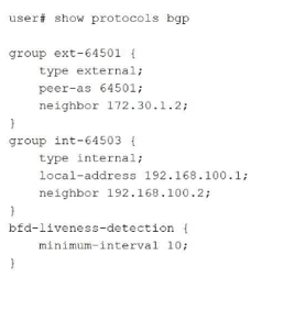
Your BGP neighbors, one in the USA and one in France, are not establishing a connection
with each other.
Referring to the exhibit, which statement is correct?
A. The BFD liveness is set too low.
B. The BFD liveness must be configured on the BGP neighbor.
C. The BFD liveness must be configured on the BGP group.
D. The BFD liveness is set too high.
Explanation:
The exhibit shows BFD liveness detection configured globally under edit protocols bgp with minimum-interval 10 milliseconds . However, this aggressive 10ms BFD timer is the direct cause of the BGP session failure between France and the United States.
Why Option A is Correct:
The BFD minimum-interval is clearly set to 10 milliseconds. For intercontinental links (USA to France), the BFD interval must be adjusted significantly upward (e.g., 300ms, 500ms, or 1000ms) to accommodate physical latency . Setting it too low causes rapid timeouts, BFD flapping, and prevents BGP from establishing a stable connection .
Why Other Options Are Incorrect:
B. The BFD liveness must be configured on the BGP neighbor.
— Incorrect. While BFD can be configured at the neighbor level, the exhibit's global configuration under protocols bgp is syntactically correct and applies to all BGP peers unless overridden . The hierarchical structure allows BFD configuration at multiple levels (protocol, group, neighbor) . The issue is the configured value, not the configuration location.
C. The BFD liveness must be configured on the BGP group.
— Incorrect. Similar to option B, BFD configuration at the protocol level (as shown) is perfectly valid and applies to the defined groups (ext-64501 and int-64503) . The bfd-liveness-detection configuration is correctly placed; relocating the same "10" value to the group level would not resolve the session establishment failure.
D. The BFD liveness is set too high.
— Incorrect. This is the opposite of the actual issue. A higher BFD interval (e.g., 1000ms) would be more tolerant of transatlantic latency. The current setting (10ms) is at the lower extreme of the configurable range (1–255,000 milliseconds) and is unsuitable for long-distance links.
Reference:
Juniper CLI Explorer: BFD parameters range 1–255,000 milliseconds
Exam Discussions: JN0-351 question analysis identifies 10ms as too low for USA-France distance
Juniper Documentation: BFD strict mode for BGP peer sessions
Exhibit
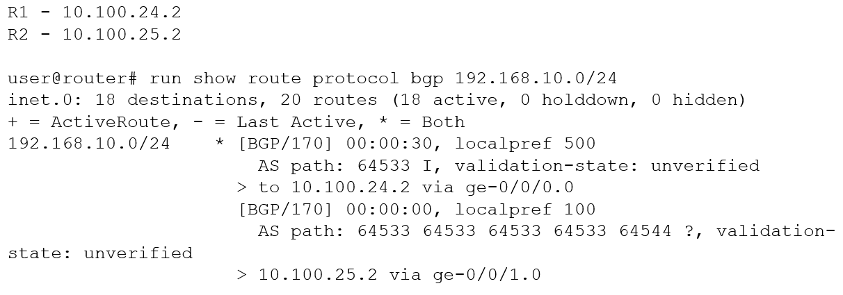
You are troubleshooting an issue where traffic to 192.168.10.0/24 is being sent to R1
instead of your desired path through R2.
Referring to the exhibit, what is the reason for the problem?
A. R2's route is not the best path due to loop prevention.
B. R2's route is not the best path due to a lower origin code.
C. R1's route is the best path due to a higher local preference
D. R1's route is the best path due to the shorter AS path.
Explanatio:
The show route protocol bgp 192.168.10.0/24 output displays two BGP routes for the same prefix. The active (best) route is marked with * and > and is via R1 (10.100.24.2). The second route via R2 (10.100.25.2) is shown but is not the active route. BGP path selection is deterministic, following a series of attributes in a specific order.
Why other options are wrong:
A. R2's route is not the best path due to loop prevention.
Incorrect. Loop prevention in BGP typically involves AS path loops (detecting own AS number in the path). The exhibit shows R2's route having multiple repetitions of AS 64533, but that alone does not indicate a loop — and even if it were a loop, the route would be hidden, not presented as an alternate. Loop prevention is not the primary reason here; local preference overrides.
B. R2's route is not the best path due to a lower origin code. Incorrect. Origin code (I vs ?) is compared after local preference, AS path length, and origin type. Even if R2 had a better origin (which it does not — ? is considered less preferred than I), local preference has already decided the winner. The statement implies origin is the reason, but it is not.
D. R1's route is the best path due to the shorter AS path.
Incorrect. R1's AS path length is 1 (just 64533). R2's AS path length is 4 (64533 64533 64533 64534). Shorter AS path is generally better, but BGP compares local preference before AS path length. Here, local preference already selects R1; the shorter AS path is consistent but not the deciding factor. The question asks for the reason given the exhibited data — localpref is the clear, highest-priority differentiator.
Reference:
Juniper TechLibrary: “BGP Path Selection Algorithm”
– “BGP selects the best route based on the following order: highest local preference, shortest AS path, lowest origin type, lowest MED, eBGP over iBGP, lowest IGP metric to next hop, lowest router ID.”
JNCIS‑ENT Study Guide (BGP chapter)
– “Local preference is the most influential attribute for outbound route selection within an AS; higher value wins.”
You are a network operator who wants to add a second ISP connection and remove the default route to the existing ISP You decide to deploy the BGP protocol in the network. What two statements are correct in this scenario? (Choose two.)
A. IBGP updates the next-hop attribute to ensure reachability within an AS.
B. IBGP peers advertise routes received from EBGP peers to other IBGP peers.
C. IBGP peers advertise routes received from IBGP peers to other IBGP peers.
D. EBGP peers advertise routes received from IBGP peers to other EBGP peers.
Explanation:
B. IBGP peers advertise routes received from EBGP peers to other IBGP peers.
This is correct. When an IBGP router receives a route from an EBGP peer, it advertises that route to all other IBGP peers within the same autonomous system (AS). This is the fundamental method for distributing external routing information throughout the AS. However, note that IBGP does not readvertise routes learned from another IBGP peer to other IBGP peers (to prevent routing loops). This is the "IBGP split horizon" rule.
D. EBGP peers advertise routes received from IBGP peers to other EBGP peers.
This is also correct. When an EBGP router receives a route from an IBGP peer (i.e., a route learned internally within the AS), it advertises that route to its EBGP neighbors in different autonomous systems. This allows external ISPs to learn about routes originated inside or transiting your AS. This is standard EBGP behavior.
Why other options are wrong:
A. IBGP updates the next-hop attribute to ensure reachability within an AS.
Incorrect. IBGP does not change the next-hop attribute by default. When an EBGP route is learned, the next-hop attribute is set to the IP address of the external neighbor. When that route is advertised via IBGP, the next-hop attribute remains unchanged. To ensure reachability within the AS, you typically need an interior gateway protocol (IGP) that has a route to that next-hop address, or you must configure next-hop self on IBGP peers. IBGP itself does not "update" the next-hop.
C. IBGP peers advertise routes received from IBGP peers to other IBGP peers.
Incorrect. This violates the IBGP split horizon rule. To prevent routing loops inside the AS, a router does not advertise an IBGP-learned route to another IBGP peer. All IBGP routers must be fully meshed (or use route reflectors or confederations) so each IBGP router receives routes directly from an EBGP router or a route reflector. Option C describes behavior that is explicitly disabled in BGP.
References:
Juniper TechLibrary: “BGP Route Advertisement Rules” – “EBGP learned routes are advertised to all IBGP and EBGP peers. IBGP learned routes are advertised only to EBGP peers, not to other IBGP peers (split horizon).”
JNCIS‑ENT Study Guide (BGP chapter) – “IBGP does not change next hop by default; IBGP split horizon prevents advertising IBGP routes to other IBGP peers.”
You are configuring a router as a new Level 1 router in an existing Level 1 area. The NET address for an existing Level 1 router is 49.0011.1111.2222.3333.00. The new router must form a Level 1 adjacency with the existing router. What should be the area ID in this scenario?
A. 00
B. 49
C. 0011
D. 3333
Explanation:
In IS-IS, each router is configured with a Network Entity Title (NET). The NET has three parts:
Area ID (variable length, 1–13 bytes)
System ID (6 bytes, or 12 hexadecimal digits)
SEL (1 byte, always 00 for routing)
The given NET for the existing Level 1 router is 49.0011.1111.2222.3333.00.
49 is the AFI (Authority and Format Identifier), not the area ID.
0011 is the area ID.
1111.2222.3333 is the system ID.
00 is the SEL.
For two routers to form a Level 1 adjacency, they must be in the same area, meaning their area IDs must match exactly. Therefore, the new router must use the area ID 0011.
Why other options are wrong:
A. 00 – Incorrect. This is the SEL (selector), used to identify OSI endpoints, not the area ID.
B. 49 – Incorrect. This is the AFI, indicating private intra‑domain routing. Routers can share AFI 49 but still be in different areas (e.g., 49.0011 vs 49.0022). The AFI alone is insufficient for Level 1 adjacency.
D. 3333 – Incorrect. This is part of the system ID (3333 is the last two bytes of the 6‑byte system ID). System IDs must be unique per router; matching this does not place routers in the same area.
References:
Juniper TechLibrary:“Understanding IS‑IS Network Entity Titles (NETs)” – “A Level 1 adjacency requires that the area IDs of the two routers match exactly. The area ID is the portion of the NET following the AFI (usually 49) and preceding the system ID.”
JNCIS‑ENT Study Guide (IS‑IS chapter) – “The NET format: AFI.areaID.systemID.SEL. For Level 1 routing, area IDs must be identical; system IDs must be unique.”
You are asked to create a default route that will be advertised to your internal OSPF neighbors. You have three upstream connections to the Internet and you must ensure that when available, all traffic uses ISP1 as your primary connection and only uses ISP2 and ISP3 when ISP1 is not available. Which solution should you implement in this scenario?
A. Create a default static route with ISP1's address as the next hop while specifying the addresses for ISP2 and ISP3 as qualified next hops with a preference value of six or higher.
B. Create a default generate route that includes an import policy to match BGP routes from ISP1 and assign a preference value of four or less.
C. Create a default static route with each neighbor address as the next hop.
D. Create a default aggregated route.
Explanation:
You need a default route (0.0.0.0/0) advertised into OSPF that prefers ISP1 primarily, with ISP2 and ISP3 as backups only when ISP1 is unavailable. This requires a static default route with multiple next hops and different preference values (administrative distance). On Juniper devices, static routes support a primary next hop and one or more qualified next hops with adjusted preference values. Lower preference is more preferred. ISP1 should have the default preference (e.g., 5 for static routes) or an explicitly lower value, while ISP2 and ISP3 should have higher preference values (e.g., 6, 7), making them less preferred. The route is then redistributed into OSPF using set protocols ospf export policy.
Why this matches option A:
Option A states: "Create a default static route with ISP1's address as the next hop while specifying the addresses for ISP2 and ISP3 as qualified next hops with a preference value of six or higher." Assuming ISP1 uses default preference (5), ISP2/ISP3 with preference 6 or higher will be used only when ISP1's next hop is unreachable. This meets the requirement exactly.
Why other options are wrong:
B. Create a default generate route that includes an import policy to match BGP routes from ISP1 and assign a preference value of four or less.
Incorrect. Generate routes are used to create aggregate-like routes based on contributing routes. Import policy filtering BGP routes does not directly control backup next hops for a single default route. Preference 4 is lower than static default (5), but this approach overcomplicates and does not clearly provide primary/backup behavior on a per‑next‑hop basis.
C. Create a default static route with each neighbor address as the next hop.
Incorrect. Without qualified next hops and different preference values, Juniper will perform equal‑cost multi‑path (ECMP) load balancing across all three next hops. This does not ensure ISP1 is always preferred when available.
D. Create a default aggregated route.
Incorrect. Aggregate routes are used to summarize specific prefixes, not to create a default route with primary/backup next hops. Aggregates do not forward traffic unless more specific contributing routes exist.
Reference:
Juniper TechLibrary: "Static Routes with Qualified Next Hops" – "Qualified next hops allow you to specify different preference values for backup paths. The route with the lowest preference is used when available."
JNCIS‑ENT Study Guide (Routing Policy & Static Routes)– "Set a primary static route (preference 5) and qualified next hops with higher preferences for failover."
Which two statements about redundant trunk groups on EX Series switches are correct? (Choose two.)
A. Redundant trunk groups load-balance traffic across two designated uplink interfaces.
B. If the active link fails, then the secondary link automatically takes over.
C. Layer 2 control traffic is permitted on the secondary link
D. Redundant trunk groups must be connected to the same aggregation switch.
Explanation:
B. If the active link fails, then the secondary link automatically takes over.
This is correct. When the active link in a redundant trunk group (RTG) fails, the secondary link immediately begins forwarding data traffic without waiting for Spanning Tree Protocol (STP) convergence, minimizing network downtime . This failover is automatic and does not require manual intervention.
C. Layer 2 control traffic is permitted on the secondary link.
This is correct. While data traffic is blocked on the secondary link, Layer 2 control traffic (such as LLDP) is still permitted to pass . This allows monitoring and management protocols to function even on the standby link, which is a key design feature of RTGs.
Why other options are wrong:
A. Redundant trunk groups load-balance traffic across two designated uplink interfaces.
Incorrect. RTGs do not perform load balancing. Data traffic is forwarded only on the active link; the secondary link remains in standby mode, blocking data traffic . This is an active/standby redundancy mechanism, not an active/active load-balancing solution.
D. Redundant trunk groups must be connected to the same aggregation switch.
Incorrect. RTGs are designed specifically for connecting an access switch to two different distribution or aggregation switches for redundancy . The example topology shows Switch 3 (access) connected to Switch 1 and Switch 2 (two separate distribution switches) . This provides device-level redundancy, which would be defeated if both links went to the same switch.
References:
Juniper TechLibrary: "Understanding Redundant Trunk Links on EX Series Switches" – "If the active link fails, the secondary link automatically starts forwarding data traffic without waiting for normal STP convergence. While data traffic is blocked on the secondary link, Layer 2 control traffic is still permitted"
Which two statements are correct about tunnels? (Choose two.)
A. BFD cannot be used to monitor tunnels.
B. Tunnel endpoints must have a valid route to the remote tunnel endpoint.
C. IP-IP tunnels are stateful.
D. Tunnels add additional overhead to packet size.
Explanation:
B. Tunnel endpoints must have a valid route to the remote tunnel endpoint.
This is correct. For any tunnel (GRE, IP-IP, MPLS, etc.), the local endpoint must have a route to the destination IP address of the remote tunnel endpoint. This route is typically through the underlying physical network. Without this, the encapsulated packets cannot be delivered to the remote peer, and the tunnel interface cannot transition to the Up state.
D. Tunnels add additional overhead to packet size.
This is correct. Tunneling encapsulates the original packet inside a new outer header (e.g., GRE adds 4 bytes; IP-IP adds 20 bytes; GRE over IPv4 adds 24 bytes total). Each tunnel type has its own encapsulation overhead. This added overhead increases the overall packet size, which can cause fragmentation if the resulting frame exceeds the MTU of the physical interface. To compensate, tunnel MTU is often reduced.
Why other options are wrong:
A. BFD cannot be used to monitor tunnels.
Incorrect. BFD (Bidirectional Forwarding Detection) can be and frequently is used to monitor tunnels. Many tunnel types, including GRE and IP-IP, support BFD over the tunnel interface. BFD provides rapid failure detection, faster than standard protocol timers (e.g., GRE keepalives or routing protocol hellos). This is a common design for high‑availability networks. Juniper devices support BFD over GRE and IP-IP tunnels.
C. IP-IP tunnels are stateful.
Incorrect. IP-IP tunnels (RFC 2003) are stateless. They simply encapsulate an IPv4 packet inside another IPv4 header with protocol 4. No state information is maintained about the tunnel session, no sequence numbers, no flow control, and no retransmission. The tunnel interface is Up as long as the endpoint IPs are reachable. In contrast, stateful tunnels (e.g., IPsec in tunnel mode with certain features) maintain security association state. IP-IP is purely stateless.
References:
Juniper TechLibrary: “Tunnel Overview” – “The tunnel source and destination addresses must be routable in the underlying network. All tunnels add encapsulation overhead.”
Juniper TechLibrary: “BFD for GRE Tunnels” – “BFD can be configured over GRE tunnels to provide fast failure detection.”
You want to use filter-based forwarding (FBF) on your Internet peering router to loadbalance traffic to two directly connected ISPs based on the source address. Which two statements are correct in this scenario? (Choose two.)
A. FBF uses the no-forwarding routing instance type.
B. FBF uses the forwarding routing instance type.
C. RIB groups are used to copy routes from the inet. o routing table.
D. RIB groups are used to hide routes in the inet. 0 routing table.
Explanation:
B. FBF uses the forwarding routing instance type.
This is correct. Filter‑Based Forwarding (FBF) is Juniper's equivalent to Policy‑Based Routing (PBR) on other platforms . To implement FBF, you create a routing instance with instance-type forwarding . This type creates a separate routing table (e.g., instance-name.inet.0) but does not require interfaces to be bound to it. Instead, interfaces remain in the default instance (inet.0), and a firewall filter redirects selected traffic to the forwarding routing instance for path selection . This is precisely what you need for source‑based load balancing between two ISPs.
C. RIB groups are used to copy routes from the inet.0 routing table.
This is correct. RIB (Routing Information Base) groups allow you to share routes between different routing tables . In an FBF scenario where you create a forwarding routing instance (e.g., ISP-A.inet.0), that instance initially has no routes. To make it functional, you need to copy the necessary routes (default routes, ISP routes) from the main routing table inet.0 into the instance's table. This is accomplished by configuring a RIB group that specifies export-rib inet.0 and import-rib [ inet.0 instance-name.inet.0 ] . The export-rib statement defines the source table from which routes are advertised .
Why other options are wrong:
A. FBF uses the no-forwarding routing instance type.
Incorrect. The no-forwarding instance type creates a separate routing table in the control plane but does not create a corresponding forwarding table in the Packet Forwarding Engine (PFE) . As confirmed by Juniper community experts, "FBF into that instance does not work by design" because there is no hardware forwarding entry for the redirected traffic to use . The no-forwarding type is useful for running multiple routing protocol instances without traffic separation, but it cannot support FBF .
D. RIB groups are used to hide routes in the inet.0 routing table.
Incorrect. RIB groups are used to copy, share, or import routes between tables — not to hide them . The export-rib statement specifies the source table for route advertisement, while import-rib specifies destination tables . Hiding routes is not a function of RIB groups; route filtering and hiding are performed using routing policies and firewall filters.
References:
Juniper CLI Explorer: "instance-type forwarding" – "Provide support for filter‑based forwarding, where interfaces are not associated with instances"
Juniper Community: "FBF and routing-instance no-forward" – "no-forwarding does not have a corresponding forwarding table, hence FBF does not work by design"
Click the Exhibit button.
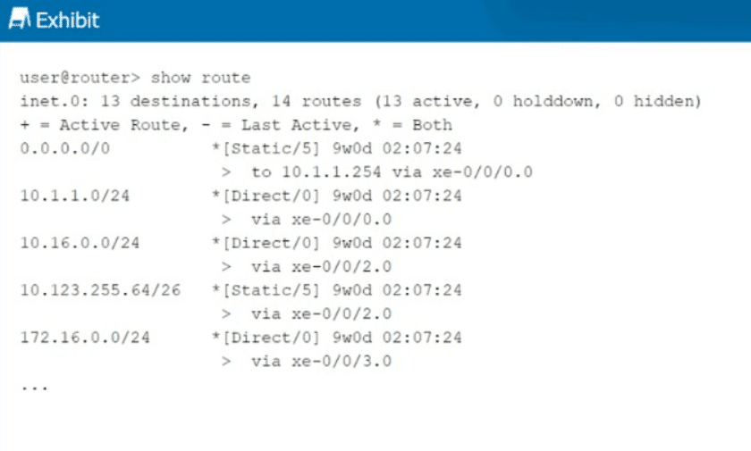
You want to redistribute the static routes into BGP, but they do not show as BGP routes.
What causes this result to occur?
A. The static routes do not have a valid next hop.
B. The as-path parameter must be specified.
C. A community string must be configured.
D. The no-readvertise feature is specified.
Explanation:
For a static route to be successfully redistributed into BGP (or any dynamic routing protocol), the route must first be active in the routing table. A route is marked as active only if its next hop is valid and recursively resolvable through other active routes in the table.
Why Other Options Are Incorrect
B. The as-path parameter must be specified.
— Incorrect. The AS path attribute is automatically added by BGP when a route is advertised. You do not need to manually specify an AS path for static routes to be redistributed into BGP.
C. A community string must be configured.
— Incorrect. BGP communities are optional transitive attributes used for tagging and policy application. They are never a requirement for redistributing static routes into BGP.
D. The no-readvertise feature is specified.
— Incorrect. The no-readvertise parameter is a specific static route option that prevents a route from being exported from the routing table into any dynamic routing protocol. If no-readvertise were configured, the static routes would still appear in show route (as they do in the exhibit), but the export policy would not be able to readvertise them. However, the question asks what causes the static routes to not show as BGP routes after attempting redistribution. While no-readvertise is a valid reason, it is not the most correct answer here because:
The question implies a general troubleshooting scenario rather than a specific misconfiguration
The exhibit shows a routing table without indicating no-readvertise is configured
With static route redistribution, the first and most common issue to verify is next-hop validity
References
Juniper TechLibrary: "Static routes are eligible to be readvertised... To mark an IPv4 static route as being ineligible for readvertisement, include the no-readvertise statement"
Pupuweb (JN0-351 exam discussion): "For successful redistribution of static routes into BGP, the static routes must have a valid next hop"
| Page 2 out of 9 Pages |
| 123 |
| JN0-351 Practice Test Home |
Real-World Scenario Mastery: Our JN0-351 practice exam don't just test definitions. They present you with the same complex, scenario-based problems you'll encounter on the actual exam.
Strategic Weakness Identification: Each practice session reveals exactly where you stand. Discover which domains need more attention, before Enterprise Routing and Switching Specialist (JNCIS-ENT) exam day arrives.
Confidence Through Familiarity: There's no substitute for knowing what to expect. When you've worked through our comprehensive JN0-351 practice exam questions pool covering all topics, the real exam feels like just another practice session.
Copyright © All Rights Reserved