Which two statements about EBGP are correct? Choose two.
A. EBGP is used between ASs.
B. EBGP is used within a single AS.
C. EBGP does not require a supporting IGP.
D. EBGP requires a supporting IGP.
Explanation:
EBGP (External Border Gateway Protocol) is the protocol used to exchange routing information between different Autonomous Systems. Unlike Internal BGP (IBGP), which functions within a single administrative domain, EBGP's primary purpose is to connect separate networks, such as connecting an enterprise data center to an ISP or connecting different stages of a Clos-based IP fabric.
Why A is correct:
By definition, External BGP sessions are established between routers with different AS numbers. This allows different organizations or network tiers to exchange reachability information while maintaining independent routing policies.
Why C is correct:
EBGP peers are typically directly connected via a shared physical link or subnet. Because they reside on the same network segment, the routers can reach each other’s interface addresses without needing an underlying Interior Gateway Protocol (IGP) like OSPF or IS-IS.
Why the other options are incorrect:
B. EBGP is used within a single AS:
This is the definition of IBGP. Routers within the same AS use IBGP to redistribute external routes learned via EBGP throughout the internal network.
D. EBGP requires a supporting IGP:
This is a requirement for IBGP, not EBGP. IBGP often relies on an IGP to provide the "underlay" reachability between loopback addresses of routers that are not physically adjacent. Since EBGP neighbors are usually directly connected, they do not need an IGP to establish their session.
References
Juniper TechLibrary - BGP Peering Sessions: Specifies that EBGP sessions connect routers in different ASs and typically use the directly connected interface addresses for peering.
RFC 4271 (A Border Gateway Protocol 4): The standard defining the behavior of BGP, highlighting the distinction between internal and external neighbors.
Which statement is correct about access ports?
A. They are assigned to a single VLAN.
B. They are assigned to multiple VLANs.
C. They must be connected to a router.
D. They must be connected to a firewall.
Explanation:
In Juniper Networks' switching architecture, an access port (or access interface) is a physical port configured to connect to an end-user device. Its primary characteristic is the handling of untagged traffic.
Why A is correct: An access port is functionally tied to one specific broadcast domain. When you configure a port in port-mode access, it is mapped to a single VLAN ID. When an untagged frame arrives from an end device (like a server or a PC), the switch automatically places that frame into the assigned VLAN. Similarly, when traffic leaves the switch through an access port, the 802.1Q VLAN tag is stripped away because the receiving end device does not expect or understand VLAN tagging. This "untagged" behavior is the standard for the vast majority of end-host connectivity in a data center.
Why the other options are incorrect:
B. They are assigned to multiple VLANs:
This describes a Trunk Port. Trunk ports are designed for switch-to-switch or switch-to-router links. They use 802.1Q tagging to carry traffic for multiple VLANs simultaneously over a single physical wire. If an access port were assigned to multiple VLANs without tagging, the switch would have no way to distinguish which broadcast domain the traffic belongs to.
C. They must be connected to a router:
While a router can be connected to an access port, it is not a requirement. Access ports are most commonly used for End Stations (servers, storage arrays, or management workstations). If a router is connected to an access port, it typically treats that link as a standard flat subnet without VLAN sub-interfaces.
D. They must be connected to a firewall:
Similar to the router explanation, a firewall is simply another type of network node. While you can connect a firewall's management or data interface to an access port, access ports are by no means exclusive to firewalls.
References
Juniper TechLibrary - Understanding Bridging and VLANs on EX Series Switches: Explicitly defines access interfaces as those that carry traffic for only one VLAN and typically connect to end-user devices.
Within OSPF, what is the purpose of a designated router DR and backup designated router BDR on a broadcast network? Choose one.
A. to reduce the resource overhead of maintaining a full mesh of adjacencies
B. to ensure that only external LSAs from other routers are directed to the correct destination
C. to coordinate routing updates to all the other routers of the point-to-point network
D. to provide a backup path in case the Designated Router goes down
Explanation:
In an OSPF (Open Shortest Path First) environment, broadcast networks (such as Ethernet) pose a unique challenge for scalability. If every router on a shared segment attempted to form an adjacency with every other router, the resulting "full mesh" would create a massive amount of redundant traffic and overhead.
Why A is correct: On a broadcast segment with $n$ routers, a full mesh would require $n(n-1)/2$ adjacencies. For example, in a segment with 10 routers, there would be 45 adjacencies and dozens of identical Link-State Advertisements (LSAs) flooding the wire. By electing a Designated Router (DR) and a Backup Designated Router (BDR), OSPF changes this topology to a "star" or "hub-and-spoke" logical model. All other routers (known as DROthers) only form full adjacencies with the DR and BDR. This significantly reduces the CPU and memory resource overhead required to maintain the Link-State Database (LSDB) and minimizes the bandwidth used for routing updates.
Why the other options are incorrect:
B. to ensure that only external LSAs are directed to the correct destination:
This is incorrect because the DR/BDR mechanism handles all types of LSAs (internal and external) within the segment. Its purpose is the management of the adjacency state, not the filtering or specific steering of external LSAs.
C. to coordinate routing updates to all the other routers of the point-to-point network:
This is a trick option. While the DR does coordinate updates, the DR/BDR mechanism does not exist on point-to-point networks. In a point-to-point link, there are only two routers, so there is no need to reduce adjacency overhead.
D. to provide a backup path in case the Designated Router goes down:
While the BDR does provide redundancy for the DR role, this is not the primary purpose of the DR/BDR system itself. The system exists to solve the scalability issue (Option A); the BDR is simply a failover mechanism for that specific solution.
References
Juniper TechLibrary - OSPF Designated Routers Overview: Explains that DRs are used to minimize the amount of network traffic and the size of the link-state database on broadcast networks.
RFC 2328 (OSPF Version 2): Section 7.3 and 7.4 detail the election and role of the DR and BDR in reducing the number of adjacencies on multi-access networks.
You want your Junos OS router to drop packets that it receives for a particular destination IP address. You also want to notify the source of the traffic that the destination IP address is unreachable. How would you accomplish this task?
A. Create a static route for the destination IP address in the inet.3 routing table.
B. Add the destination IP address to the list of martian IP addresses.
C. Create a static route for the destination IP address with a next hop of reject.
D. Create and apply a firewall filter to the ingress interface that discards traffic destined to the IP address.
Explanation:
In Junos OS, you can control how the router handles traffic for specific destinations by using special "discard" or "reject" next hops within a static route.
Why C is correct: When you configure a static route with a next hop of reject, the router performs two actions:
It drops the packet (it is not forwarded).
It sends an ICMP "destination unreachable" message back to the source of the traffic.
This fulfills both requirements of the prompt: dropping the packet and notifying the sender. If you had chosen a next hop of discard, the packet would be dropped silently without notifying the source.
Why the other options are incorrect:
A. Create a static route in the inet.3 routing table:
The inet.3 table is specifically used for MPLS path information and RSVP/LDP signaling. It is not the primary table used for standard IPv4 unicast forwarding (which is inet.0). Adding a route here would not achieve the goal of dropping and notifying general traffic.
B. Add the destination IP address to the list of martian IP addresses:
"Martian" addresses are IP addresses that are inherently invalid for routing (such as 0.0.0.0/8 or 127.0.0.0/8). While you can add addresses to this list to prevent them from being installed in the routing table, it is a global security setting rather than a method for targeted traffic rejection and ICMP notification.
D. Create and apply a firewall filter with the discard action:
A firewall filter with the discard action will drop the packet, but it does so silently. To notify the source via a firewall filter, you would need to use the reject action. However, the most direct and standard way to handle a specific destination prefix for unreachability in a routing context is via a static route.
References
Juniper TechLibrary - Static Routes Overview: Explains the difference between the discard next hop (silent drop) and the reject next hop (drop with ICMP unreachable message).
Junos OS Routing Protocols Configuration Guide: Section on "Static Routes," detailing the use of special next hops for traffic engineering and security.
Referring to the exhibit,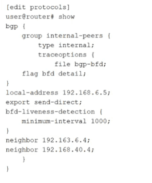
how much time must pass before a neighbor is considered down?
A. 5000 ms
B. 2000 ms
C. 1000 ms
D. 3000 ms
Explanation:
In Junos OS, Bidirectional Forwarding Detection (BFD) is used to provide rapid failure detection for routing protocols like BGP. The total time required to declare a neighbor "down" (the Detection Time) is not based solely on the transmission interval; it is a calculation involving both the interval and a multiplier.
Why the other options are incorrect:
A. 5000 ms: This would imply a multiplier of 5, which is not the Junos default.
B. 2000 ms: This would imply a multiplier of 2. While commonly used in some low-latency designs, it must be manually configured.
C. 1000 ms: This is the interval itself. If the neighbor were declared down after only 1000 ms, the system would have a multiplier of 1, providing no margin for minor network jitter or brief packet loss.
References:
Juniper TechLibrary - BFD for BGP Overview: Details how BFD liveness detection works and how it integrates with BGP to trigger fast rerouting.
Junos OS Routing Protocols Configuration Guide: Section on "BFD Liveness Detection Operations," which explicitly states that the detection time equals the transmission interval multiplied by the detection time multiplier (defaulting to 3).
What are three correct layer names used in legacy hierarchical network design? (Choose three.)
A. Access layer
B. Modular layer
C. Aggregation layer
D. Core layer
E. Function layer
Explanation:
The legacy hierarchical model (often referred to as the Cisco Three-Layer Model or the Classic Tiered Design) was the standard for campus and data center networks before the widespread shift toward Spine-Leaf architectures.
Access Layer (A):
This is the network edge where end devices (servers, workstations, and printers) connect to the network. Its primary role is to provide a point of entry for user traffic and enforce security policies like Port Security or 802.1X.
Aggregation Layer (C):
Traditionally called the Distribution layer, this tier acts as the boundary between the L2 access domain and the L3 routed core. It aggregates traffic from multiple access switches, performs routing, and enforces inter-VLAN communication and Quality of Service (QoS) policies.
Core Layer (D):
This is the high-speed backbone of the network. Its sole purpose is to switch packets as fast as possible between aggregation blocks. It is designed for high availability and low latency, typically avoiding CPU-intensive packet manipulation.
Why the other options are incorrect:
B. Modular layer:
While network designs can be "modular" in philosophy (the "Building Block" approach), there is no specific "Modular layer" in the formal hierarchical model.
E. Function layer:
This is not a recognized term in the classic three-tier hierarchy. Specific "functions" (like management or services) may exist in a network, but they do not constitute a primary design layer.
References
Juniper TechLibrary - Data Center Architecture Overview: Discusses the evolution from traditional three-tier hierarchical designs (Access, Aggregation, Core) to modern fabric designs.
JNCIA-DC Exam Objectives (JN0-281): Covered under Data Center Architectures, specifically comparing legacy tiered models with modern IP Fabrics.
What are two challenges of traditional data center architectures? Choose two.
A. inefficient resource usage
B. inefficient network path selection
C. isolated user devices
D. increased latency
Explanation:
Traditional data center architectures, often built on a three-tier hierarchical model (Access, Aggregation, and Core), were designed primarily for North-South traffic (traffic entering or leaving the data center). However, modern workloads involve heavy East-West traffic (server-to-server), which reveals the following challenges:
Why B is correct:Traditional designs rely heavily on the Spanning Tree Protocol (STP) to prevent loops in Layer 2 networks. STP works by blocking redundant links, which leads to inefficient network path selection. Only one path is active at a time, meaning expensive bandwidth on "blocked" links sits idle, and traffic often takes a sub-optimal, circuitous route to avoid loops.
Why D is correct: In a multi-tier hierarchy, traffic moving between two servers in different segments often has to travel "up" to the Aggregation or Core layer and then back "down" to the destination. This "trombone" or "hairpin" effect results in increased latency and puts unnecessary load on the higher-tier switches. Modern Spine-Leaf architectures solve this by ensuring every leaf is only one hop away from every other leaf.
Why the other options are incorrect:
A. Inefficient resource usage:
While related to the waste of bandwidth caused by STP, "inefficient resource usage" is a broad term often associated with server virtualization or power consumption rather than being a specific architectural network challenge defined in the context of JNCIA-DC.
C. Isolated user devices:
Traditional architectures were actually quite effective at connecting devices; the issue wasn't isolation, but rather the efficiency and speed of the communication between those devices once connected.
References:
Juniper TechLibrary - Understanding IP Fabrics:Compares traditional tiered designs with modern fabrics, highlighting the limitations of STP and the latency issues in hierarchical models.
Junos OS Data Center Fundamentals: Discusses the shift from North-South optimized designs to East-West optimized Spine-Leaf designs to reduce hop counts.
You are troubleshooting BGP routing and want to verify that you are sending a default route to peer address 10.100.25.6. Which command would satisfy the requirement?
A. show route protocol bgp 0.0.0.0
B. show route receive-protocol bgp 10.100.25.6 0.0.0.0
C. show route protocol static 0.0.0.0
D. show route advertising-protocol bgp 10.100.25.6 0.0.0.0
Explanation:
When troubleshooting BGP in Junos OS, it is critical to distinguish between what the router knows (its routing table) and what it is actually communicating to its neighbors.
Why D is correct: The command show route advertising-protocol bgp
Why B is incorrect: The receive-protocol command shows you the routes that the neighbor is sending to you (ingress). This would verify if the neighbor is advertising a default route to your router, rather than the other way around.
Why A is incorrect: This command simply displays whether a BGP-learned default route exists in your own local routing table (inet.0). It does not confirm whether that route is being successfully advertised to a peer.
Why C is incorrect: This checks for a locally configured static default route. While a static route is often the source of a default route advertisement, seeing it in the static table does not mean the BGP process has been configured to export it.
References
Juniper TechLibrary - Verifying BGP Routes: Explains the usage of advertising-protocol and receive-protocol for verifying route exchange between BGP peers.
Junos OS Operational Mode Commands: Details the syntax for the show route hierarchy, specifically how to filter by neighbor and prefix.
Which BGP attribute is used to prevent routing loops in a network?
A. MED
B. LOCAL_PREF
C. NEXT_HOP
D. AS_PATH
Explanation:
The AS_PATH attribute is BGP's standard loop‑prevention mechanism. When a BGP router receives an update, it examines the AS_PATH sequence. If the router finds its own AS number already listed, it immediately discards the route. This rejection occurs because the route has already exited that AS and is trying to re‑enter, which would create a routing loop. Without AS_PATH loop detection, BGP routes could cycle indefinitely between ASes.
Why other options are incorrect (briefly):
A. MED (Multi‑Exit Discriminator)
– Used by an AS to suggest a preferred entry path to neighboring ASes. It influences inbound traffic selection but has no loop‑detection capability.
B. LOCAL_PREF
– Used only within an AS to select the best outbound route to a destination. It is not exchanged between eBGP peers, so it cannot prevent loops across different ASes.
C. NEXT_HOP
– Specifies the next‑hop IP address to forward traffic toward a destination. Incorrect NEXT_HOP can break reachability, but it does not perform any loop‑checking function.
Additional context for the exam:
In a data center fabric running EBGP as the underlay (common in IP fabrics / Clos designs), AS_PATH loop prevention ensures that routes do not circle back through spine or leaf devices. For iBGP within the same AS, loop prevention is handled by split‑horizon rules (not AS_PATH), making AS_PATH specifically critical for eBGP scenarios.
References
Juniper TechLibrary – BGP Loop Detection
"If a BGP device receives a route that contains its own AS number in the AS_PATH, it rejects the route as a loop."
RFC 4271, Section 9.1.2 (BGP-4)
"If the AS_PATH attribute of a BGP route contains the local AS number, the route MUST NOT be considered further.
What are two names used to refer to the Layer 2 table that maintains known switching information? Choose two.
A. inet.0 table
B. routing information base RIB
C. Ethernet switching table
D. forwarding information base FIB
Explanation:
The Layer 2 table that maintains known switching information (MAC addresses, associated VLANs, and egress interfaces) is referred to by two common names in Juniper networks and industry standards.
C. Ethernet switching table
– This is the descriptive, platform-neutral name for the table. It stores MAC address to port mappings. When a switch receives a frame, it looks up the destination MAC in this table to determine where to forward the frame (unicast, flood, or discard).
D. forwarding information base (FIB)
– In Junos OS, the FIB is the actual hardware-forwarding table used by the Packet Forwarding Engine (PFE). For Layer 2 switching, the FIB contains the learned MAC addresses and their associated interfaces. While many associate FIB with Layer 3 routing, in a switching context, the Layer 2 FIB is the operational table that drives frame forwarding decisions.
Why the other options are incorrect (briefly):
A. inet.0 table
– This is a Junos routing table for IPv4 unicast routes (Layer 3). It stores IP prefixes and next-hop information, not MAC addresses or switching information.
B. routing information base (RIB)
– The RIB is a control-plane table (e.g., inet.0, inet6.0) that stores routing information learned from routing protocols or static configuration. The RIB is not a Layer 2 switching table; it feeds into the FIB but does not itself maintain MAC forwarding entries.
References:
Juniper TechLibrary – Layer 2 Forwarding
"The Ethernet switching table (also known as the MAC address table or Layer 2 FIB) contains MAC addresses and their associated VLAN and interface information."
JNCIA-DC Certification Guide, Domain 2 (Data Center Switching)
"The forwarding information base (FIB) for Layer 2 is the MAC forwarding table, also called the Ethernet switching table."
Which feature should be used with a static route that has a secondary next hop with a unique route preference value? Choose one.
A. retain
B. resolve
C. qualified next hop
D. install
Explanation:
In Junos OS, when you need to configure a static route that has a secondary next hop with a unique route preference value, you use the qualified next-hop feature.
The qualified next-hop statement allows you to associate different preference (administrative distance) values with different next-hop addresses for the same destination prefix. The primary next hop uses the default static route preference (typically 5 for IPv4 or 10 for IPv6, depending on Junos version), while each qualified next hop can have its own preference value. The route with the lowest preference value is installed into the forwarding table.
This is commonly used for floating static routes (backup routes). For example, you can configure an Ethernet link as the primary path with preference 5, and a secondary path (e.g., a slower backup link) as a qualified next hop with preference 12. The backup route only becomes active when the primary route fails.
Why other options are incorrect (briefly):
A. retain
– This option keeps a static route in the routing table even if the next hop becomes unreachable. It does not allow per-next-hop preference configuration.
B. resolve
– This allows a static route's next hop to be indirectly resolved through another route in the routing table. It does not provide secondary next hops with unique preferences.
D. install
– This forces a static route into the forwarding table even if its preference is not the best. It does not enable multiple next hops with different preference values.
References:
Juniper TechLibrary – Qualified Next Hops for Static Routes
"You can specify a preference value for each qualified next hop, which allows you to control which next hop is selected as active."
JNCIA-DC Certification Guide, Domain 3 (Routing)
"Qualified next hops allow a static route to have multiple secondary paths, each with its own preference. This provides granular control over route failover."
Which statement is correct about building an IP fabric?
A. Each spine device should have a direct physical connection to every other spine device.
B. Each spine device should have a direct physical connection to every leaf device.
C. Each spine device must have two or more physical connections to each leaf device.
D. Each spine device must have two or more physical connections to every other spine device.
Explanation:
In a standard IP fabric (also known as a Clos or spine‑leaf architecture) used in modern data centers, the design follows a simple, non‑blocking topology:
Spine layer – Acts as the aggregation/core, providing high‑speed interconnectivity.
Leaf layer – Connects to servers, storage, or network services.
The fundamental rule is: Every spine device connects to every leaf device, and no direct spine‑to‑spine or leaf‑to‑leaf connections are required (though leaf‑to‑leaf may exist via the spine). This creates a full bipartite mesh between the two layers. Each spine sees all leaves, and each leaf sees all spines.
Why B is correct:
Each spine device must have a direct physical link to every leaf device to ensure that any leaf can reach any other leaf through at most two hops (leaf → spine → leaf). This provides predictable latency, easy scaling (add spines or leaves independently), and ECMP (Equal‑Cost Multi‑Path) benefits.
Why other options are incorrect (briefly):
A. Each spine device should have a direct physical connection to every other spine device.
– Incorrect. Spine‑spine connections are not part of a standard IP fabric. They would create a traditional multi‑tier core, not a Clos fabric, and can introduce unnecessary complexity and forwarding loops.
C. Each spine device must have two or more physical connections to each leaf device.
– Incorrect. While redundancy is good practice (e.g., two links from a leaf to each spine for bandwidth and resilience), it is not a requirement of the IP fabric definition. The fabric only requires at least one connection per spine‑leaf pair.
D. Each spine device must have two or more physical connections to every other spine device.
– Incorrect. Spine‑spine links are not part of the IP fabric model and are unnecessary. Adding them would break the fabric’s simplicity and ECMP symmetry.
References:
Juniper TechLibrary – IP Fabric Underlay
"In a spine‑leaf IP fabric, each spine device is connected to every leaf device. No spine‑to‑spine or leaf‑to‑leaf links are required."
JNCIA-DC Certification Guide, Domain 4 (Data Center Fabrics)
"A Clos IP fabric requires full‑mesh connectivity between the spine and leaf layers. Adding spines increases capacity and redundancy without affecting existing leaves."
| Page 1 out of 6 Pages |
| 12 |
Real-World Scenario Mastery: Our JN0-281 practice exam don't just test definitions. They present you with the same complex, scenario-based problems you'll encounter on the actual exam.
Strategic Weakness Identification: Each practice session reveals exactly where you stand. Discover which domains need more attention, before Data Center Associate (JNCIA-DC) exam day arrives.
Confidence Through Familiarity: There's no substitute for knowing what to expect. When you've worked through our comprehensive JN0-281 practice exam questions pool covering all topics, the real exam feels like just another practice session.
Copyright © All Rights Reserved