
You recently enabled ARP protection on your CX switches, but many users now complain that they can no longer access the network. What do you need to configure to resolve the issue?
A. Dynamic IP lockdown
B. IGMP snooping
C. DHCP snooping
D. DHCP reservations
Explanation:
Dynamic ARP Protection (also called ARP inspection) validates ARP packets by checking every IP-to-MAC binding against a trusted binding database. This database is populated by DHCP snooping, which intercepts DHCP exchanges and records the valid IP-to-MAC leases.
If you enable ARP protection without DHCP snooping configured, the switch has no binding database to validate ARP traffic against. As a result, it treats all ARP packets from untrusted ports as invalid and drops them, causing users to lose network connectivity. The DHCP snooping binding table is the only source of binding information used by ARP inspection.
How to Resolve the Issue
- Enable DHCP snooping globally on the switch.
- Enable DHCP snooping on each VLAN where clients reside.
- Configure trusted ports for the DHCP server and any uplinks or inter-switch links.
This allows the switch to build a valid IP-to-MAC binding table from observed DHCP exchanges. ARP protection can then correctly validate ARP packets against this table.
Why Other Options Are Incorrect
A. Dynamic IP lockdown:
This is a separate security feature that restricts client traffic based on the DHCP snooping binding table. It does not provide the binding database that ARP protection requires.
B. IGMP snooping:
This is used for multicast traffic optimization, not ARP or DHCP security.
D. DHCP reservations:
Reservations are configured on the DHCP server, not on the switch. They do not help the switch validate ARP packets locally.
Key Concept: The Dependency Relationship
DHCP snooping:
Builds and maintains the IP-to-MAC binding database.
ARP protection (ARP inspection):
Validates ARP packets against the DHCP snooping binding database.
Dynamic IP lockdown:
Filters data traffic based on the DHCP snooping binding database.
ARP protection cannot function without a populated binding database—which is why DHCP snooping must be configured first. This is the root cause of the connectivity loss described in the question.
An HPE Aruba Networking CX switch is configured with IGMP using the given output:
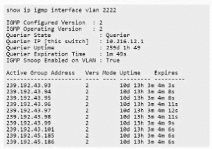
Which statement is true about the possible supported message types?
A. Leave and Report
B. Join, Leave, Query and Report
C. Query and Report
D. Join and Query
Explanation:
The output shows that the switch is running IGMP version 2 and is operating as the IGMP querier.
For IGMPv2, HPE Aruba documentation describes the relevant IGMP message functions as:
Query:
Sent by the querier to determine whether multicast receivers are still present.
Report (Join):
Sent by a host to indicate that it wants to join, or remains a member of, a multicast group.
Leave Group:
Sent by an IGMPv2 host when it leaves a multicast group.
HPE Aruba specifically describes the message types as “Query, Report (Join), and Leave Group.”
In exam terminology, Join is often listed separately even though technically the join operation is performed by sending an IGMP Membership Report. Therefore, option B represents all the applicable IGMPv2 message behavior.
Why the other options are incorrect
A. Leave and Report:
Missing Query.
C. Query and Report:
Missing Leave, which is supported by IGMPv2.
D. Join and Query:
Missing the Leave operation.
HPE Aruba's multicast best-practice documentation also confirms that an IGMPv2 querier handles membership queries, membership reports/joins, and leave-group messages.
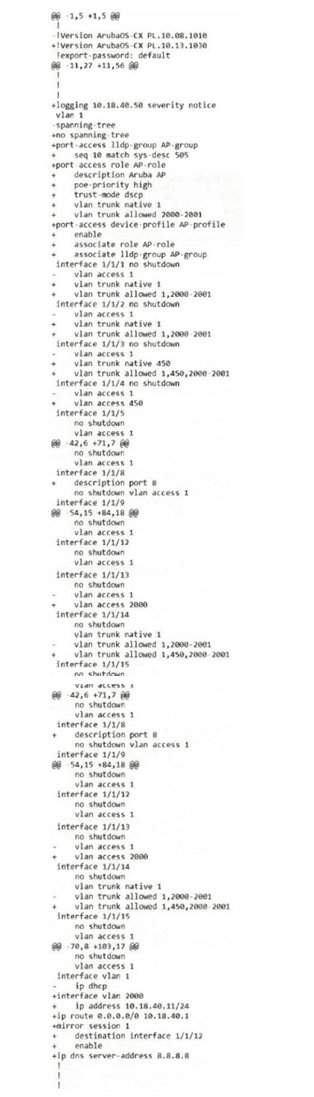
Based on the images provided , which CLI command was used to produce this output?
A. Use checkpoint diff to compare running-config with stored checkpoints.
B. Use show checkpoint compare to compare running-config with stored saved-config revisions.
C. Use show checkpoint diff to compare running-config with stored checkpoints.
D. Use checkpoint compare to compare running-config with stored saved-config revisions.
Explanation:
The output shown uses +/- line prefixes to indicate additions and removals between two configurations — this is the classic format produced by ArubaOS-CX's checkpoint diff functionality. The command syntax on ArubaOS-CX is:
switch# show checkpoint diff running-config <checkpoint-name>
or similarly comparing two checkpoints:
switch# show checkpoint diff checkpoint-name-1 checkpoint-name-2
This command compares the running-config (the active configuration currently in memory) against a stored checkpoint (a saved configuration snapshot, such as startup-config or a manually created checkpoint). The output format uses:
+ : Indicates lines present in the running-config but not in the checkpoint (additions).
- : Indicates lines present in the checkpoint but not in running-config (removals/changes).
@@ : Markers indicate line-position/context information, similar to a standard diff output — exactly as shown in the exhibit.
Why not the others:
A. checkpoint diff:
This is not valid ArubaOS-CX syntax; the command must be invoked under the show context as show checkpoint diff, not as a standalone checkpoint diff command.
B. show checkpoint compare (vs. saved-config):
ArubaOS-CX does not use the term "compare" or reference "saved-config revisions" in this context; the correct keyword is diff, and comparisons are against checkpoints, not a generic "saved-config" revision system.
D. checkpoint compare (vs. saved-config revisions):
Same issue as B, combined with the invalid standalone (non-show) command structure as in A.
Since the output format (unified diff style with +/-/@@) directly matches the show checkpoint diff command comparing running-config to a stored checkpoint, Option C is correct.
Your customer’s CX switches are managed in HPE Aruba Networking Central. They have recently deployed new cabling to some desks and want to be notified of any physical cabling issues. Which alerts should you enable? (Choose two.)
A. Switch Port Input Errors
B. Switch Port Rx Rate
C. Switch Hardware Failure
D. Switch Uplink Port Usage
E. Switch Port Duplex Mode
Explanation
Physical cabling problems (bad cables, damaged connectors, incorrect cable type/length, poor terminations, etc.) commonly manifest as:
- Input errors (CRC errors, alignment errors, runts, giants, etc.) on the switch ports.
- Duplex mismatches (the port falling back to half-duplex), which is frequently caused by auto-negotiation failures due to cabling issues.
In HPE Aruba Networking Central, the two alerts that directly detect these conditions are:
Switch Port Input Errors:
Triggers when the percentage of input errors on a port exceeds the configured threshold. This is the primary indicator of Layer-1 cabling problems.
Switch Port Duplex Mode:
Triggers when a port is operating in half-duplex mode (instead of the expected full-duplex). Half-duplex operation is a classic symptom of cabling or negotiation issues.
Why the other options are not appropriate
B. Switch Port Rx Rate:
Monitors traffic volume/utilization, not physical errors.
C. Switch Hardware Failure:
Covers broader hardware events (fans, power supplies, temperature, etc.). While some cable-related symptoms can appear under hardware failure categories, it is not the specific, targeted alert for port cabling issues.
D. Switch Uplink Port Usage:
Tracks bandwidth utilization on uplinks, not physical-layer problems.
Recommendation:
Enable both Switch Port Input Errors and Switch Port Duplex Mode alerts (and set appropriate thresholds) so the customer is proactively notified of any physical cabling problems on the newly deployed desk connections.
You are attempting to configure an interface, but you are seeing the error message below.
What could explain this?
Access-1(config)# interface 1/1/1
Invalid input: interface
A. The switch is in password recovery mode
B. The command must be run from the manager context
C. The switch is being managed by HPE Aruba Networking Central
D. Authorization is enabled for CLI commands
Explanation:
When an ArubaOS-CX switch is managed by Aruba Central, certain configuration commands can become restricted or hidden from the local CLI, depending on the management mode (e.g., template-based/overlay management). In these scenarios, Central becomes the source of truth for configuration, and some commands — particularly those Central manages centrally through templates or group-based configuration — will return an "Invalid input" error when attempted locally via CLI, even though the command syntax itself is completely correct. This is because the switch's CLI parser has that portion of the command set disabled/restricted while under Central's management, rather than returning a permission-style error.
This matches the scenario exactly: interface 1/1/1 is valid, standard ArubaOS-CX syntax, yet it's rejected as "Invalid input" — indicating the command is not being recognized/available in the current operating context, which points to Central management restricting local configuration ability.
Why not the others:
A. Password recovery mode:
In password recovery mode, the switch boots into a special recovery context specifically for resetting credentials; you wouldn't be able to reach a normal (config)# prompt and attempt interface configuration in the first place, so this doesn't fit the scenario shown.
B. Must be run from manager context:
The prompt shown, Access-1(config)#, already indicates the switch is in global configuration context (reached after configure terminal), which is exactly where interface commands are meant to be run in ArubaOS-CX. There's no separate "manager context" requirement for this command in ArubaOS-CX.
D. Authorization enabled for CLI commands:
If TACACS+/RADIUS command authorization were blocking this command, the switch would typically return a permission-denied / authorization failure message, not "Invalid input" (which specifically indicates a syntax/command-recognition issue, not an authorization rejection).
Since the symptom is the command being unrecognized rather than denied, and this is a well-documented behavior of Central-managed switches, Option C is correct.
You have configured UBT on your CX switches, but now HTTPS-enabled websites will not load, which you suspect is due to the packet size. To resolve the issue, what should you configure on each device with funneled traffic?
A. Path MTU discovery
B. Fragment reassembly
C. Jumbo frames
D. IP fragmentation
Explanation
Why it is correct:
When User-Based Tunneling (UBT) is enabled, user data packets are encapsulated in GRE/IP tunnels, which adds extra header overhead and increases the overall packet size. If the resulting packets exceed the path Maximum Transmission Unit (MTU) and fragmentation is disabled or blocked (often causing issues with secure HTTPS traffic due to TLS record sizes), websites fail to load. Configuring or permitting IP fragmentation ensures that oversized encapsulated packets are properly split and successfully delivered across the path.
Why others are incorrect:
- Path MTU discovery relies on ICMP messages, which are frequently blocked by modern firewalls, leading to black-holed traffic.
- Fragment reassembly happens on the receiving end rather than being a mitigation configuration on the transmitting/tunneling device.
- Jumbo frames require end-to-end infrastructure support and do not resolve overhead issues across standard routed intermediate paths.
You recently made a configuration change on a switch, and shortly afterward, you noticed a spike in CPU utilization in the NAE dashboard. You are concerned that the high CPU could be affecting users. What should you do to restore service as quickly as possible?
A. Reboot the switch
B. Revert the change
C. Disable debug logging
D. Pause NAE monitoring
Explanation:
Because the CPU spike appeared shortly after a configuration change, the fastest way to restore normal operation is to roll back or revert that change.
On Aruba AOS-CX, configuration checkpoints and rollback features are designed specifically for situations like this. Reverting the recent change can quickly return the switch to the previously stable state without the disruption of a full reboot.
Why the other options are incorrect
A. Reboot the switch:
More disruptive and may not solve the issue if the problematic configuration remains in place.
C. Disable debug logging:
Useful only if excessive debugging is known to be causing the CPU load. The question points to the recent configuration change as the likely cause.
D. Pause NAE monitoring:
This would stop monitoring but would not address the underlying high-CPU condition affecting users.
Your customer's CX switches are managed in HPE Aruba Networking Central. If a VSX primary switch is accidentally powered off, which alert will be triggered?
A. Switch Reboot
B. Switch Stack Conductor Change
C. Switch Disconnected
D. Switch STP Root Change
Explanation:
In a VSX pair, the primary and secondary switches operate as separate devices. If the primary switch is accidentally powered off, HPE Aruba Networking Central detects that the switch has lost connectivity and triggers a Switch Disconnected alert.
This is different from a VSF stack, where a conductor change can occur if the stack's conductor switch fails.
Why the other options are incorrect
A. Switch Reboot:
Indicates a switch reboot event, not simply loss of connectivity due to power-off.
B. Switch Stack Conductor Change:
Applies to a VSF stack conductor change, not a VSX primary switch failure.
D. Switch STP Root Change:
Occurs when the spanning-tree root bridge changes, which is not the direct event described.
Exam takeaway:
VSX primary switch powered off → Central detects the switch going offline → Switch Disconnected alert.
A customer wants to prevent 'man-in-the-middle' attacks based on Layer 2 addressing. What will help address that concern?
A. Enable ARP inspection in the VLAN interface context
B. Enable ARP inspection in the VLAN context
C. Enable ARP inspection in the global context
D. Enable ARP inspection in interface-level context
Explanation
To protect a Layer 2 network from ARP spoofing and man-in-the-middle attacks, administrators deploy Dynamic ARP Inspection (DAI) on HPE Aruba Networking CX switches.
Why it is correct:
In ArubaOS-CX, DAI operates on a per-VLAN basis. To enable the feature, you must enter the specific VLAN configuration mode (config-vlan) and issue the arp inspection command. This tells the switch to inspect and validate all ARP packets on that VLAN against trusted database bindings (such as DHCP snooping or static IP-to-MAC bindings).
Why the other options are incorrect:
- VLAN interface context (SVI) is used for layer-3 routing addresses, not Layer 2 security features like DAI.
- Global context is used for system-wide parameters, whereas DAI is toggled selectively per VLAN.
- Interface-level context (physical ports/LAGs) is used to configure whether a specific port is trusted (arp inspection trust), but it does not enable the inspection engine itself.
Reference
ArubaOS-CX IP Services Guide – Dynamic ARP Inspection & arp inspection Command Reference.
You are implementing a design where the campus network should be in an isolated spanning tree topology from the data centre network. The core switches are connected by a single Layer-2 interface carrying multiple VLANs. When you examine the switches, you discover that the campus core sees the data centre core as the root bridge. What configuration can you apply to the campus-to-data centre core link to resolve the issue?
A. Root guard
B. BPDU filter
C. Admin edge
D. BPDU guard
Explanation:
The requirement is to keep the campus network and data center network as isolated/independent spanning tree topologies, but they are physically connected by a single Layer-2 trunk link. Since STP BPDUs are being exchanged across this link, the campus core is seeing the data center core as root — meaning the two networks are effectively merging into a single spanning tree domain, rather than staying isolated as intended.
Root Guard, applied on the campus-side port(s) of that link, is designed exactly for this situation: it enforces that a specific port can never become a root port — meaning the switch will never accept superior BPDUs (i.e., claims of being a better/lower root bridge) arriving on that port. If a superior BPDU is received (as would happen if the data center core is advertising itself as root), Root Guard puts that port into a "root-inconsistent" (blocking) state, preventing the campus switch from accepting the data center as its root bridge, while still allowing the link to pass data once the BPDU consistency issue is resolved, or by design for boundary enforcement. This effectively preserves the campus network's own independent STP topology and root bridge.
This is the standard best-practice mechanism for maintaining STP domain boundaries on links between two administratively separate networks (e.g., campus vs. data center), ensuring one side can never dictate root bridge election for the other.
Why not the others:
B. BPDU filter:
This suppresses BPDU transmission/processing entirely on a port, effectively removing STP protection on that link. This is dangerous on an inter-core trunk carrying multiple VLANs, since it could create loops if the topology isn't otherwise fully controlled — not the correct tool for boundary/root isolation.
C. Admin edge (edge port / PortFast):
This is meant for access ports connecting to end-user devices (not other switches), enabling the port to skip the STP listening/learning states for fast connectivity. It is not intended for switch-to-switch core links, and does not address root bridge isolation.
D. BPDU guard:
This is used on edge ports to immediately err-disable the port if any BPDU is received at all (protecting against unauthorized switches being plugged into access ports). Applying this on a core inter-switch trunk would completely shut down that critical link the moment BPDUs are exchanged — not appropriate for a legitimate switch-to-switch connection carrying real STP traffic.
Since the goal is to block the data center from being seen as root while keeping the link operational for actual traffic, Root Guard (A) is the correct, purpose-built solution.
Your customer’s CISO would like to deploy colorless ports across the network. Which will you need to configure to meet this requirement?
A. 802.1Q
B. 802.1X
C. 802.11X
D. 802.1AD
Explanation:
Colorless ports are a feature that simplifies network access by allowing any device to connect to any switch port and receive the appropriate network access based on its identity, rather than the port it is plugged into.
This is achieved by configuring the switch port to authenticate devices using 802.1X (and often MAC Authentication as a fallback). When a device connects, the switch challenges it for credentials, and upon successful authentication, a RADIUS server (such as HPE Aruba Networking ClearPass) sends back a user role or VLAN assignment that is applied to that specific port dynamically.
The official HPE Aruba documentation explains that with colorless ports, "all ports on an access switch are set to authenticate with both 802.1X and MAC Authentication. When a device connects to the network it is authenticated using either MAC Authentication or 802.1X and triggers an enforcement policy from ClearPass".
Why Other Options Are Incorrect
A. 802.1Q:
802.1Q is the VLAN tagging standard used on trunk links. It is not the authentication mechanism that enables colorless ports.
C. 802.11X:
802.11 is the standard for wireless networking (Wi-Fi), not wired port authentication.
D. 802.1AD:
802.1AD is the standard for Provider Bridging (Q-in-Q), used for service provider networks, not for port access control.
Key Concept
Colorless ports rely on port access authentication (802.1X / MAC Authentication) coupled with a RADIUS server like ClearPass to dynamically assign roles and VLANs. This allows the network to treat all ports identically while still enforcing security policies based on who or what connects.
References
- HPE Aruba Networking AOS-CX Security Guide: Protocol and feature details for Dynamic Segmentation
- HPE Aruba Networking Central: Configuring Authentication on AOS-CX
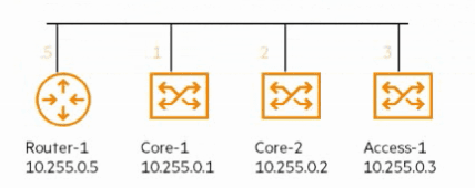
You are configuring OSPF on each of the devices shown. After verifying the OSPF
neighbor table on each, you notice that Router-1 and Access-1 have neighbors in the
2WAY state. What is the reason for this?
A. Router-1 and Access-1 have reached a tie in the DR election
B. Router-1 and Access-1 have no OSPF networks to advertise
C. This is normal behavior for OSPF neighbors on a broadcast network
D. IGMP snooping has been configured on Router-1 and Access-1
Explanation:
Option C (Correct):
On broadcast multi-access networks (like Ethernet), OSPF forms full adjacencies only with the Designated Router (DR) and Backup Designated Router (BDR). All other neighbors remain in the 2WAY state. This is expected behavior and prevents unnecessary full adjacencies between every device, reducing overhead. Router-1 and Access-1 are not DR/BDR, so their adjacency stays at 2WAY.
Option A:
A tie in DR election does not result in a permanent 2WAY state. OSPF resolves DR/BDR elections deterministically (highest priority, then highest router ID).
Option B:
Even if they had no networks to advertise, OSPF adjacency states would still progress beyond 2WAY if they were DR/BDR. The lack of advertised networks does not explain the state.
Option D:
IGMP snooping is unrelated to OSPF neighbor states. It deals with multicast traffic management, not routing protocol adjacencies.
Reference
- RFC 2328 – OSPF Version 2: Section 7.3 on neighbor states (2WAY state on broadcast networks).
- Aruba CX OSPF Configuration Guide – Explains DR/BDR election and adjacency formation.
- HPE7-A08 Exam Objectives: Domain 3.0 – OSPF Neighbor States and Adjacency.
| Page 2 out of 11 Pages |
| 1234 |
| HPE7-A08 Practice Test Home |
Real-World Scenario Mastery: Our HPE7-A08 practice exam don't just test definitions. They present you with the same complex, scenario-based problems you'll encounter on the actual exam.
Strategic Weakness Identification: Each practice session reveals exactly where you stand. Discover which domains need more attention, before HPE Aruba Networking Certified Professional - Switching exam day arrives.
Confidence Through Familiarity: There's no substitute for knowing what to expect. When you've worked through our comprehensive HPE7-A08 practice exam questions pool covering all topics, the real exam feels like just another practice session.
Copyright © All Rights Reserved