
Plan and Design the VMware Solution
An administrator has been tasked with deploying a new VMware Cloud Foundation (VCF) environment that
includes a Management Domain and two workload domains. Compliance regulations require that production
and non-production workloads reside in separate failure domains, with the production workload environment
using low-latency block storage and the non-production environment relying on high-capacity file-based
storage.
Which combination of supported non-vSAN storage solutions should the administrator recommend to meet
these requirements?
A. Management domain on vVols over NFS, production workload domain on VMFS over iSCSI, and nonproduction workload domain on SMB
B. Management domain on local VMFS datastores, production workload domain on iSCSI, and nonproduction workload domain on NFS v3
C. Management domain on vSAN ESA, production workload domain on vSAN HCI Mesh, and nonproduction workload domain on vSAN File Services
D. Management domain on VMFS over Fibre Channel, production workload domain on VMFS over NVMe/FC, and non-production workload domain on NFS v4.1
Explanation:
The question evaluates supported non-vSAN principal storage options in VMware Cloud Foundation 9.0. It focuses on separating production and non-production workloads into different failure domains while meeting specific performance needs: low-latency block storage for production and high-capacity file storage for non-production.
✅ Correct Option:
D. Management domain on VMFS over Fibre Channel, production workload domain on VMFS over NVMe/FC, and non-production workload domain on NFS v4.1
This option meets all requirements. VMFS over Fibre Channel is supported as principal storage for the Management Domain in greenfield deployments. VMFS on NVMe/FC delivers the low-latency block storage needed for production workloads. NFS v4.1 provides high-capacity file-based storage for non-production, ensuring separate failure domains.
❌ Incorrect options:
A. Management domain on vVols over NFS, production workload domain on VMFS over iSCSI, and nonproduction workload domain on SMB
vVols is not recommended as principal storage for the Management Domain. SMB is not supported as principal storage in VCF. iSCSI has restrictions for greenfield principal deployments in this context.
B. Management domain on local VMFS datastores, production workload domain on iSCSI, and nonproduction workload domain on NFS v3
Local VMFS datastores are not supported as principal storage for the Management Domain, which requires shared storage. iSCSI is not available as principal storage for greenfield Management Domain deployments.
C. Management domain on vSAN ESA, production workload domain on vSAN HCI Mesh, and nonproduction workload domain on vSAN File Services
This solution is fully vSAN-based, which does not satisfy the non-vSAN requirement. It fails to provide separate external block and file storage for distinct failure domains.
🔧 Reference:
→ VMware Cloud Foundation 9: Now Ready For All Storage
Confirms expanded non-vSAN support including FC VMFS for Management Domain.
→ Storage Models - VCF 9.0 Documentation
Details principal storage options like Fibre Channel, NVMe/FC, and NFS protocols.
An administrator is monitoring a vSAN ESA backed workload domain that is dedicated for running AI
inferencing. When the administrator navigates to the Storage Performance dashboard in VMware Cloud
Foundation Operations, the performance dashboard shows:
• High backend write latency ( > 8 ms)
• Low read latency ( < 1 ms)
• Normal network throughput
• Disk Group Health = Green
Based on the readings above, what would be the explanation?
A. This is caused due to transient commit-queue delays, since the workload is exhibiting random-writes saturating ESA’s write buffer.
B. A wrongly sized read cache tier is throttling the write buffer, thus forcing the reads to trespass to the capacity tier.
C. The workload’s small-block writes are compressed inline, lowering backend throughput and increasing cache misses.
D. A vSAN network congestion event on the vSAN TCP port 2233 is throttling mirror acknowledgements.
Explanation:
This question tests understanding of vSAN Express Storage Architecture (ESA) performance characteristics and how storage metrics should be interpreted. The key indicators are high backend write latency, low read latency, normal network throughput, and healthy disk groups, which point toward a write-intensive workload rather than a network or hardware problem.
🟢 Correct Option:
A. This is caused due to transient commit-queue delays, since the workload is exhibiting random-writes saturating ESA’s write buffer.
The metrics indicate that reads are being served efficiently while writes are experiencing delays. Since network throughput is normal and storage health remains green, the issue is unlikely to be hardware or network related. AI inferencing workloads can generate bursts of metadata and random write operations that temporarily increase backend write latency. Such conditions can create commit-queue delays as ESA processes and persists incoming writes, resulting in elevated write latency without affecting read performance.
🔴 Incorrect Options:
B. A wrongly sized read cache tier is throttling the write buffer, thus forcing the reads to trespass to the capacity tier.
vSAN ESA does not use the traditional cache-and-capacity architecture found in vSAN Original Storage Architecture (OSA). The observed low read latency also contradicts the claim that reads are being forced into a slower storage tier. The performance data does not indicate a read-path bottleneck.
C. The workload’s small-block writes are compressed inline, lowering backend throughput and increasing cache misses.
ESA performs efficient data services such as compression, but compression alone does not typically create the observed pattern of high write latency with consistently low read latency. Furthermore, cache misses are not reflected in the provided metrics and would likely impact read performance as well.
D. A vSAN network congestion event on the vSAN TCP port 2233 is throttling mirror acknowledgements.
The dashboard explicitly reports normal network throughput, which makes network congestion an unlikely cause. If mirror acknowledgements were being delayed by network issues, additional network-related symptoms would be expected, including elevated communication latency and broader storage performance degradation.
🔧 Reference:
⇒ vSAN ESA Performance and Architecture Overview
Explains ESA architecture, write handling, and performance behavior under write-intensive workloads.
⇒ Monitoring vSAN Performance Metrics
Describes interpretation of latency, throughput, and health metrics when analyzing vSAN performance issues.
A VMware Cloud Foundation (VCF) Management Domain is requested to be deployed with the following
information:
. 6 blade style hosts with no local storage beyond the operating system.
. 4 25 Gb networking cards installed in each host.
. A 30 TB external array configured to support NVMe/TCP only.
. 2 dVS switches, one configured for storage isolation and one for all other traffic.
. Aria Operations is not currently deployed in the environment.
Place the general steps in sequence for converging VCF on to this configuration.
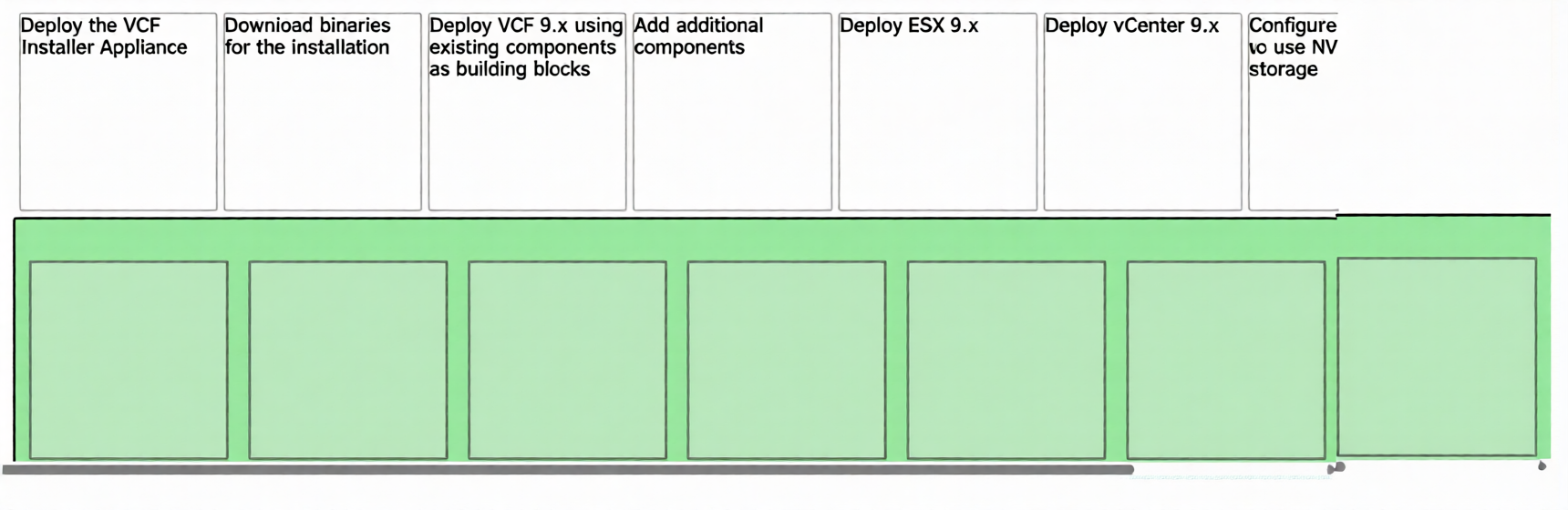
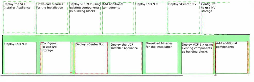
Explanation:
This question tests knowledge of the VCF 9.0 "converge" workflow for greenfield deployments where NVMe/TCP principal storage is required. Since NVMe/TCP is not available in automated greenfield workflows, the correct sequence follows VMware's documented process: first build the vSphere foundation manually, then use VCF Installer to convert it into a VCF management domain .
✔️ Step 1 (Deploy ESX 9.x):
For NVMe/TCP principal storage, the process begins by manually installing ESXi 9.x on all 6 blade hosts. This establishes the hypervisor layer before any storage or management components can be configured .
✔️ Step 2 (Configure to use NV storage):
NVMe/TCP storage must be configured at the ESXi host level before vCenter deployment. This involves configuring NVMe/TCP adapters, discovering NVMe namespaces, and presenting the 30 TB external array to all hosts .
✔️ Step 3 (Deploy vCenter 9.x):
After ESXi hosts have access to the NVMe/TCP storage, deploy the vCenter Server 9 appliance on one of the hosts. The vCenter must be placed on a datastore residing on the pre-configured NVMe/TCP storage .
✔️ Step 4 (Deploy the VCF Installer Appliance):
With vCenter managing the ESXi cluster and NVMe/TCP datastores, download and deploy the VCF Installer appliance. VCF Installer 9.0 replaces the older Cloud Builder appliance used in previous versions .
✔️ Step 5 (Download binaries for the installation):
Before initiating the converge workflow, use VCF Installer to download all necessary installation binaries for VCF components, including SDDC Manager and NSX .
✔️ Step 6 (Deploy VCF 9.x using existing components as building blocks):
Execute the "Converge" workflow within VCF Installer, pointing it to the existing vCenter. This converts the vSphere environment into a VCF management domain and uses the pre-configured NVMe/TCP datastore as principal storage .
✔️ Step 7 (Add additional components):
After successful converge, add additional components such as NSX networking, configure the second distributed vSwitch for storage isolation, and optionally deploy Aria Operations if required .
❌ Common Sequencing Errors to Avoid:
Deploy VCF Installer first:
Deploying the VCF Installer appliance before ESXi hosts and storage configuration is incorrect because the installer's converge workflow requires an existing vSphere environment with configured storage to operate on .
Missing NVMe/TCP configuration order:
Configuring NVMe/TCP storage after vCenter deployment is invalid because vCenter deployment requires an accessible datastore. The storage must be presented to ESXi hosts before vCenter installation .
Placing VCF deployment before component downloads:
Attempting to deploy VCF 9.x before downloading binaries would fail because the installation artifacts are not yet available locally. Download must precede deployment .
🔧 Reference:
→ Broadcom Support KB 416270: Supporting all Principal Storage Options in VMware Cloud Foundation 9 – Confirms the complete converge workflow for NVMe/TCP principal storage including manual ESXi deployment, storage configuration, vCenter deployment, then VCF Installer converge.
→ Broadcom TechDocs: VCF Installer – Details the VCF Installer appliance deployment and converge workflow for converting existing vSphere environments.
An administrator is responsible for a VMware Cloud Foundation (VCF) Private Cloud and has been tasked
with identifying and explaining the different Fibre Channel (FC) Storage Area Network (SAN) components
within a VCF Workload Domain cluster.
Drag and drop the correct Term onto its matching Definition.
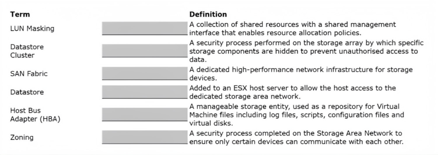
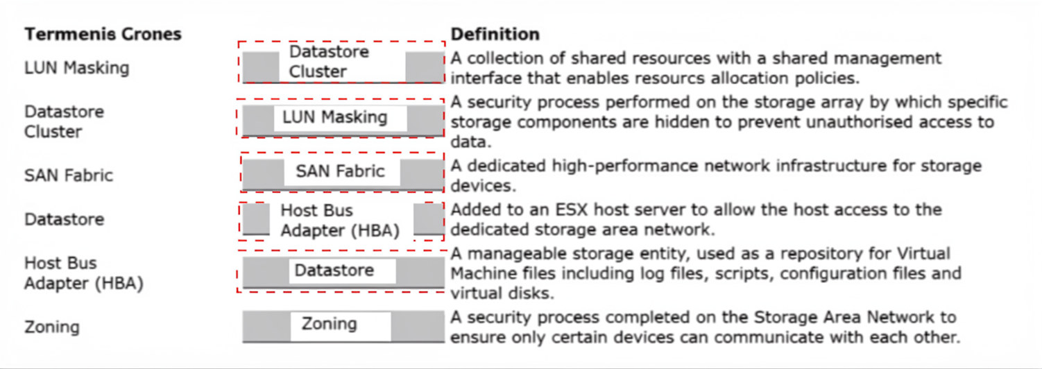
Explanation:
This question tests an administrator's understanding of foundational storage technologies, specifically relating to Fibre Channel (FC) Storage Area Networks (SAN) and VMware vSphere constructs. Accurately mapping these storage terms is necessary for configuring, managing, and securing non-vSAN external block storage within a VCF Workload Domain.
✅ Correct Option:
Datastore Cluster
A collection of shared resources with a shared management interface that enables resource allocation policies. This fits perfectly because a Datastore Cluster aggregates multiple physical datastores into a single logical unit, enabling automated storage management features like Storage DRS for balance and capacity allocation.
LUN Masking
A security process performed on the storage array by which specific storage components are hidden to prevent unauthorized access to data. This is the exact definition as LUN masking is an array-level permission mechanism ensuring that only designated ESXi host initiators can see and access specific Logical Unit Numbers (LUNs).
SAN Fabric
A dedicated high-performance network infrastructure for storage devices. This matches the definition as the SAN fabric comprises the physical hardware components—such as Fibre Channel switches, routers, and data links—that route storage traffic network-wide between server hosts and target storage arrays.
Host Bus Adapter (HBA)
Added to an ESXi host server to allow the host access to the dedicated storage area network. This is completely accurate because an HBA is the specialized physical interface card installed within the server hardware that connects the ESXi host operating system directly to the Fibre Channel network.
Datastore
A manageable storage entity, used as a repository for Virtual Machine files including log files, scripts, configuration files, and virtual disks. This fits because a VMware datastore is the logical storage container (formatted with VMFS) that abstracts underlying physical storage to safely house active VM components.
Zoning
A security process completed on the Storage Area Network to ensure only certain devices can communicate with each other. This is correct because FC zoning is managed at the fabric switch level, segmenting the network into isolated zones to control device visibility and interaction between hosts and storage arrays.
❌ Incorrect options:
Misplaced Definitions / Incorrect Pairings
Mapping any term to a different slot fails because each operational layer is distinct. Mixing switch-level fabric security (Zoning) with array-level target security (LUN Masking), or confusing physical server hardware (HBA) with software storage repositories (Datastore), introduces architectural errors that violate core vSphere storage administration rules.
🔧 Reference:
⇒ VMware vSphere Storage Guide
→ Validates standard definitions and configuration rules for Fibre Channel SAN components, Host Bus Adapters, LUN management, and Datastore structures within vSphere environments.
An administrator has successfully deployed a vSAN Stretched Cluster and needs to ensure that any Virtual
Machines (VMs) that are created are placed in the appropriate site.
Which two steps are required to complete the task? (Choose two.)
A. Put the VMs in the correct DRS Group.
B. Create a VM/Host group across the two sites.
C. Create VM/Host groups for the two sites.
D. Put the VMs in the correct VM Folder.
E. Create a storage policy for each site.
Explanation:
This question tests the administrator's understanding of how to enforce site affinity in a vSAN Stretched Cluster environment. To ensure VMs are placed and remain on the correct site, administrators must use DRS VM/Host Groups combined with VM-Host Affinity Rules — a standard vSphere mechanism for controlling workload placement across stretched cluster sites.
✅ Correct Options:
C. Create VM/Host groups for the two sites.
Before any affinity rules can be applied, the administrator must first create separate VM Groups and Host Groups for each site (Site A and Site B). These groups logically define which hosts belong to which site and which VMs should be associated with them. This is the foundational step for enforcing site-aware placement in a stretched cluster.
A. Put the VMs in the correct DRS Group.
Once VM/Host groups are created, the administrator must assign each VM to the appropriate VM DRS group corresponding to its intended site. This, combined with a VM-Host Affinity Rule, ensures DRS enforces placement and keeps VMs running on hosts within their designated site during normal operations and after failover recovery.
❌ Incorrect Options:
B. Create a VM/Host group across the two sites.
VM/Host groups should be created per site, not across both sites. Creating a single group spanning both sites defeats the purpose of site isolation and affinity enforcement. Stretched cluster best practices require distinct, separate groups for each site to ensure correct placement and DRS rule targeting.
D. Put the VMs in the correct VM Folder.
VM Folders are purely an organizational and inventory management tool within vCenter. They have no influence over DRS placement decisions, host affinity, or site preference in a stretched cluster. Placing VMs in folders does not control or enforce which physical site the VM runs on.
E. Create a storage policy for each site.
While storage policies are important for defining vSAN data placement and protection (such as site affinity in storage), they do not control compute placement of VMs across sites. A storage policy alone cannot ensure a VM runs on hosts at a specific site — that requires DRS groups and affinity rules.
🔧 Reference:
⇒ VMware vSAN Stretched Cluster Guide – Administering VMware vSAN → Confirms that VM/Host Groups and DRS Affinity Rules are required to enforce site-specific VM placement in stretched clusters.
⇒ VMware vSphere DRS – vSphere Resource Management → Validates the process of creating VM Groups, Host Groups, and affinity rules to control workload placement across defined host groups.
An administrator is tasked with deploying a VMware Cloud Foundation (VCF) Workload Domain that meets
the following requirements:
• vSAN ESA as principal storage
• RAID-6 with FTT=2
• Support for Storage Traffic Separation
The administrator is provided the following hardware to perform the task:
• Four ESX hosts, each host contains:
24 CPU cores
96 GB memory
Two 25GbE network NICs
12 NVMe devices 4 TB each, connected to a single SATA/SAS/NVMe Tri-mode controller What four changes must the administrator make to the hardware before deploying the new Workload Domain?
(Choose four.)
A. Increase the ESX host count to a minimum of seven.
B. Increase the ESX host count to a minimum of six.
C. Increase the CPU quantity on each host to a minimum 32.
D. Increase the Tri-mode controller quantity on each host to two, with six NVMe devices connected to each.
E. Increase the network NICs on each host to minimum of four 25 GbE network NICs.
F. Replace the network NICs on each host to a minimum of two 100 GbE network NICs.
G. Increase the memory on each host to a minimum 128 GB.
H. Replace the Tri-mode controller on each host with a dedicated NVMe controller.
Explanation:
This question tests knowledge of vSAN ESA ReadyNode and VMware Cloud Foundation hardware requirements. The workload domain must support vSAN ESA, RAID-6 (FTT=2), and Storage Traffic Separation (STS). The provided hardware does not meet several minimum requirements, so the administrator must modify the configuration before deployment can proceed successfully.
🟢 Correct Option:
B. Increase the ESX host count to a minimum of six.
vSAN ESA RAID-6 with FTT=2 requires sufficient hosts to tolerate multiple failures while maintaining data availability and compliance with the selected storage policy. A four-host cluster is insufficient for this design requirement. Expanding the cluster to at least six hosts provides the capacity and fault-domain support needed for ESA RAID-6 configurations in a VCF workload domain.
🟢 Correct Option:
D. Increase the Tri-mode controller quantity on each host to two, with six NVMe devices connected to each.
vSAN ESA supports NVMe devices behind certified controllers, but large numbers of drives attached to a single controller can create bottlenecks. Distributing the twelve NVMe devices across two controllers improves performance, resiliency, and compliance with validated ESA hardware designs. This configuration aligns with supported ReadyNode guidance for enterprise ESA deployments.
🟢 Correct Option:
E. Increase the network NICs on each host to minimum of four 25 GbE network NICs.
Storage Traffic Separation requires dedicated network paths for different traffic types, including vSAN and vMotion. With only two NICs, there is insufficient network redundancy and traffic segregation capability. Increasing to four 25 GbE adapters enables the administrator to implement separated traffic flows while maintaining high availability and performance for the ESA workload domain.
🟢 Correct Option:
G. Increase the memory on each host to a minimum 128 GB.
The supplied hosts contain only 96 GB of memory, which falls below the minimum memory requirement for ESA-based workload domain deployments. Increasing memory to at least 128 GB ensures compliance with VCF and ESA hardware requirements while providing sufficient resources for storage services and workload operations.
🔴 Incorrect Options:
A. Increase the ESX host count to a minimum of seven.
While seven hosts would support the workload, it is not the minimum change required. The requirement is to meet supported deployment standards, and six hosts are sufficient for the specified ESA RAID-6 and FTT=2 configuration.
C. Increase the CPU quantity on each host to a minimum 32.
The provided 24-core processors do not violate ESA deployment requirements. vSAN ESA does not mandate a minimum of 32 CPU cores per host for the described configuration, making this upgrade unnecessary.
F. Replace the network NICs on each host to a minimum of two 100 GbE network NICs.
vSAN ESA benefits from high-speed networking, but 100 GbE adapters are not required for Storage Traffic Separation. Supported designs can meet the requirements using additional 25 GbE adapters, making this replacement unnecessary.
H. Replace the Tri-mode controller on each host with a dedicated NVMe controller.
vSAN ESA supports certified Tri-mode controllers when used in validated hardware configurations. The issue is the controller layout and drive distribution rather than the controller technology itself. Replacing the controller is not required.
🔧 Reference:
⇒ VMware Cloud Foundation 9 Storage and vSAN ESA Requirements
Confirms hardware, networking, and storage requirements for VCF workload domains using vSAN ESA.
⇒ vSAN ESA Planning and Deployment Guide
Provides guidance on ESA cluster sizing, RAID-6 requirements, controller design, and Storage Traffic Separation prerequisites.
An administrator notices alerts triggering IOPS and Disk Throughput storage performance problems in the
Fibre Channel datastore in a VMware Cloud Foundation (VCF) Workload Domain.
What can the administrator review to identify which Virtual Machines (VMs) may be experiencing storage
IOPS and disk throughput performance issues?
A. vSAN Health dashboard.
B. vSphere Storage Inventory dashboard.
C. Live! vSphere Heavy Hitter VM dashboard.
D. Storage Operations page.
Explanation:
The question tests knowledge of monitoring tools in VMware Cloud Foundation to identify individual VMs causing high IOPS and disk throughput issues on a Fibre Channel datastore.
✅ Correct Option:
C. Live! vSphere Heavy Hitter VM dashboard.
This dashboard is designed to highlight VMs with the highest storage resource consumption. It provides real-time visibility into IOPS, throughput, and latency at the VM level, allowing administrators to quickly pinpoint which VMs are contributing to performance alerts on traditional datastores like Fibre Channel VMFS.
❌ Incorrect options:
A. vSAN Health dashboard.
This dashboard is specific to vSAN clusters and focuses on vSAN health, capacity, and object compliance. It does not monitor performance of external Fibre Channel datastores or individual VM IOPS.
B. vSphere Storage Inventory dashboard.
This provides an overview of storage inventory, capacity, and general health but does not offer detailed per-VM IOPS or throughput analysis for identifying heavy hitters.
D. Storage Operations page.
The Storage Operations page gives high-level cluster and datastore performance KPIs (IOPS, throughput, latency) but lacks granular VM-level breakdown to identify specific problematic virtual machines.
🔧 Reference:
→ VCF Operations - Storage Performance Monitoring
Confirms use of Heavy Hitter dashboards for VM-level storage performance analysis.
A storage architect is designing a vSAN solution that enforces quotas and Access Based Enumeration (ABE)
on all file shares.
What should the architect highlight as a design decision implication?
A. When creating the share, enable quotas and ABE under SMB settings.
B. Quotas are supported only on NFS shares; ABE is supported only on SMB shares.
C. Deploy separate file services servers, one for quotas and one for ABEs.
D. Quotas and ABEs must be configured at a cluster level and not per-share.
Explanation:
This question tests knowledge of vSAN File Services quota and Access Based Enumeration (ABE) configuration. The architect needs to understand where and how these features are applied. The search results from official VMware/Broadcom documentation confirm that both quotas and ABE are configured on a per-share basis during share creation, specifically within SMB share settings .
✔️ Option A (When creating the share, enable quotas and ABE under SMB settings):
The official vSAN File Services documentation confirms that both quotas and Access Based Enumeration are configured on a per-file share basis . When creating an SMB share, administrators can set share warning thresholds and share hard quotas under "Storage space quotas" . The ABE option, which hides files and folders users lack permission to access, appears exclusively under SMB protocol settings .
❌ Option B (Quotas supported only on NFS; ABE supported only on SMB):
This is incorrect. Official Broadcom documentation confirms that storage space quotas (both warning threshold and hard quota) are available for both NFS and SMB shares when creating a file share . ABE is indeed only available for SMB shares , but the statement about quotas is false.
❌ Option C (Deploy separate file services servers for quotas and ABEs):
This is incorrect. vSAN File Services does not require separate servers for quotas versus ABE functionality. The file service architecture places file service VMs (FSVMs) on each host, and each FSVM contains a file server that provides both NFS and SMB services . Quotas and ABE are feature settings, not infrastructure components requiring dedicated servers.
❌ Option D (Quotas and ABEs must be configured at cluster level, not per-share):
This is incorrect. Official Broadcom documentation explicitly states that quotas can be enabled on a "per-file share basis" . The vSAN API documentation for VsanFileShareConfig shows quota is a property of individual file share configurations . ABE is also selected individually for each SMB share during creation, not at the cluster level .
🔧 Reference:
→ Broadcom TechDocs: Create a vSAN File Share – Confirms storage space quotas (warning threshold and hard quota) and Access Based Enumeration for SMB shares are configured per-share during creation.
→ Broadcom VMware Docs: vSAN File Services – Confirms quotas on a per-file share basis and ABE as a security mechanism for SMB shares.
An administrator has been tasked with making changes to a VMware Cloud Foundation (VCF) Workload
Domain cluster that is configured with NFS for both Principal storage and Supplemental storage.
The cluster has the following configuration:
• There are 3 x ESX host servers.
• There are 3 x NFS Datastores allocated to host Virtual Machines workloads.
• There is a single NFS Datastore allocated for hosting ISO files.
The administrator has the following concerns with the existing configuration:
• Every time a new Virtual Machine is deployed to the Workload Domain, the administrator must choose
which datastore should be used.
• When reviewing the Datastores in VCF Operations:
One of the datastores has no Virtual Machines running in it.
The other two datastores have an imbalance of Virtual Machines and this is causing resource
contention. The administrator has the following requirements: • Virtual Machines must be placed
automatically on the most appropriate datastore based on utilization. • Migration recommendations on
Virtual Machine placement should be made when one datastore reaches 50% utilization. • Virtual
Machines must only be migrated to another datastore after being approved by an administrator. What
four actions must the administrator take to meet all of the requirements? (Choose four.)
A. Configure the Datastore Cluster to set the Storage DRS storage space threshold to 50%.
B. Configure the Datastore Cluster to set the Storage DRS storage space utilization difference to 50%.
C. Create a new Datastore Cluster using all three NFS Datastores allocated to host Virtual Machines workloads.
D. Configure the Datastore Cluster to use Fully Automated Storage DRS.
E. Ensure all three NFS Datastores are available to each ESX host server.
F. Configure the Datastore Cluster to use Manual Storage DRS.
G. Create a new Datastore Cluster using all four available Datastores.
Explanation:
This question tests the administrator's ability to correct resource imbalances and automate placement within a VCF Workload Domain using Storage DRS (SDRS). It requires grouping identical workload datastores, ensuring proper host presentation, setting explicit capacity utilization triggers, and selecting the appropriate automation level based on administrative approval policies.
✅ Correct Option:
A. Configure the Datastore Cluster to set the Storage DRS storage space threshold to 50%.
The requirements state that migration recommendations must be generated when a datastore hits 50% utilization. Configuring the Storage DRS space utilization threshold specifically to 50% ensures that the SDRS engine evaluates the cluster and alerts the administrator as soon as any single datastore reaches this exact capacity.
C. Create a new Datastore Cluster using all three NFS Datastores allocated to host Virtual Machines workloads.
To solve the issue of manual datastore selection and resource imbalance, the three active VM workload datastores must be aggregated into a single logical Datastore Cluster. The ISO datastore must be excluded from this cluster because it serves a different functional purpose and should not hold running VM workloads.
E. Ensure all three NFS Datastores are available to each ESX host server.
For a Datastore Cluster to function reliably and allow safe VM migrations or automated placements, uniform storage connectivity is required. Every ESXi host within the VCF Workload Domain cluster must have simultaneous access to all three participating NFS datastores to prevent dead-ends or access loss during placement.
F. Configure the Datastore Cluster to use Manual Storage DRS.
The prompt explicitly dictates that Virtual Machines must only be migrated to another datastore after being approved by an administrator. Choosing Manual mode ensures that Storage DRS runs its algorithms and populates clear placement and migration recommendations but waits for explicit administrative sign-off before executing them.
❌ Incorrect options:
B. Configure the Datastore Cluster to set the Storage DRS storage space utilization difference to 50%.
Setting the space utilization difference to 50% would mean SDRS only reacts if the capacity gap between the most filled and least filled datastore exceeds 50%. This does not satisfy the requirement to trigger migration recommendations the moment an individual datastore reaches 50% total utilization.
D. Configure the Datastore Cluster to use Fully Automated Storage DRS.
Fully Automated SDRS allows vSphere to automatically execute initial placements and migrate running virtual machines between datastores without any human intervention. This directly violates the strict corporate constraint stating that no VM migrations can happen without manual approval from an administrator.
G. Create a new Datastore Cluster using all four available Datastores.
Including the dedicated ISO datastore inside the VM Datastore Cluster is an architectural error. The ISO repository holds static media files and is not configured for highly active, low-latency VM disk workloads; mixing it into the cluster would cause SDRS to mistakenly place active virtual machines on it.
🔧 Reference:
⇒ VMware vSphere Storage Guide
→ Confirms how to configure Datastore Clusters, set Storage DRS capacity thresholds, and implement Manual vs. Automated migration recommendations based on business rules.
An administrator is deploying a vSphere Supervisor Cluster on a VMware Cloud Foundation (VCF)
Workload Domain that uses NFS storage. As part of the configuration, the administrator must define separate
storage policies for container images, ephemeral volumes, and persistent volumes within the vSphere
Namespace.
The solution must align with vSphere Storage Policy Based Management (SPBM) and Broadcom TechDocs
recommendations for supported Supervisor configurations.
Which configuration meets these requirements?
A. Create three SPBM storage policies that all reference the same shared NFS datastore. Assign these policies respectively to container images, ephemeral volumes, and persistent volumes when enabling Workload Management to logically isolate the volume types within a single datastore.
B. Use datastore clusters to automatically balance storage consumption for container and persistent volumes, and rely on vSphere DRS to place ephemeral data dynamically across datastores.
C. Create three distinct SPBM storage policies mapped to shared NFS datastore(s). Assign the policies to the corresponding storage options for container images, ephemeral volumes, and persistent volumes.
D. Define one default storage policy and allow the Supervisor control plane to automatically create subpolicies for container and persistent workloads during namespace provisioning.
Explanation:
This question tests your understanding of vSphere Storage Policy Based Management (SPBM) configuration for vSphere Supervisor Clusters with Tanzu. The administrator must create separate storage policies for container images, ephemeral volumes, and persistent volumes, and assign them to the corresponding storage options when enabling Workload Management on a VCF Workload Domain using NFS storage.
✔️ Option C (Correct):
Creating three distinct SPBM storage policies mapped to shared NFS datastore(s) is correct because vSphere with Tanzu requires separate storage policies for control plane VMs, pod ephemeral disks, and container image cache when configuring the Supervisor Cluster. Each policy represents datastore(s) and manages storage placement for specific workload types. Container images, ephemeral volumes, and persistent volumes each have different storage requirements and lifecycle characteristics. Assigning distinct policies to the corresponding storage options ensures proper placement and management of each workload type according to Broadcom TechDocs recommendations for supported Supervisor configurations.
❌ Option A (Incorrect):
Creating three SPBM storage policies that all reference the same shared NFS datastore is incorrect because while logically isolating volume types within a single datastore is possible, the option's phrasing suggests the policies don't provide actual separation. The key requirement is to create distinct policies that map to datastores and assign them to corresponding storage options. Simply referencing the same datastore in three policies doesn't align with best practices for different storage classes. The policies should represent different storage capabilities or classes (Bronze, Silver, Gold) rather than just three labels for the same datastore.
❌ Option B (Incorrect):
Using datastore clusters to automatically balance storage consumption and relying on vSphere DRS is incorrect because vSphere with Tanzu and Supervisor Clusters require explicit SPBM storage policies, not DRS-based automatic placement. DRS doesn't manage Kubernetes storage objects like ephemeral disks, container images, or persistent volumes. SPBM is the required framework for integrating with shared datastores (VMFS, NFS, vSAN, vVols) and managing placement of control plane VMs, pod ephemeral disks, container images, and persistent volumes. Automatic DRS placement doesn't provide the policy-driven storage management required for Supervisor Cluster configurations.
❌ Option D (Incorrect):
Defining one default storage policy and allowing the Supervisor control plane to automatically create subpolicies is incorrect because vSphere with Tanzu requires administrators to create storage policies before enabling the Supervisor Cluster. The control plane doesn't automatically create subpolicies for container and persistent workloads during namespace provisioning. Each storage type (control plane VMs, ephemeral disks, container image cache, persistent volumes) needs explicit policy assignment. The vSphere administrator must define storage policies describing different storage requirements and classes of services, then assign them to vSphere Namespaces.
🔧 Reference:
→ vSphere with Tanzu Storage
Confirms that storage policies represent datastores and manage placement of control plane VMs, pod ephemeral disks, container images, and persistent volumes
→ Change Storage Settings on Supervisor Cluster
Confirms administrators configure SPBM storage policies when enabling Supervisor Cluster for control plane, ephemeral disks, and container image cache
An administrator reports that after rebooting one host in a vSAN cluster configured with Data-at-Rest
Encryption using an external Key Management Server (KMS), the host shows all vSAN disk groups as
unmounted.
The KMS is online and reachable from all hosts.
In vCenter, the host displays the following event:
“Failed to retrieve encryption key from KMS.”
Key ID:
All other hosts in the cluster remain healthy and show “Encryption: Enabled.”
Why did the encryption key retrieval fail for this host?
A. The host’s trust relationship or certificate with the KMS is invalid or missing.
B. The cluster requires a Deep Rekey operation to restore access to the encrypted disks.
C. The vCenter Server has not been restarted to refresh the encryption key cache.
D. The TPM on the host failed to unlock the data encryption keys.
Explanation:
This question tests the administrator's understanding of how vSAN Data-at-Rest Encryption authenticates with an external KMS. The scenario isolates the issue to a single host after a reboot, while the KMS is reachable and all other hosts are healthy — pointing directly to a host-level trust or certificate problem, not a cluster-wide or KMS-side failure.
✅ Correct Option:
A. The host's trust relationship or certificate with the KMS is invalid or missing.
In vSAN encryption with an external KMS, each ESXi host must maintain its own trusted certificate relationship with the KMS to independently retrieve encryption keys. After a reboot, if the host's KMS certificate is expired, missing, or revoked, the host cannot authenticate and key retrieval fails. Since only this host is affected and the KMS is online, the trust/certificate relationship is the definitive root cause.
❌ Incorrect Options:
B. The cluster requires a Deep Rekey operation to restore access to the encrypted disks.
A Deep Rekey operation re-encrypts data with a new Key Encryption Key (KEK) and is used proactively for key rotation — not for troubleshooting key retrieval failures on a single host. It would not resolve a certificate or trust issue and is irrelevant when only one host fails while others remain healthy.
C. The vCenter Server has not been restarted to refresh the encryption key cache.
vCenter Server does not cache or distribute encryption keys to ESXi hosts in external KMS configurations. Each host communicates directly and independently with the KMS. Restarting vCenter would have no impact on a host's ability to retrieve its encryption key from the KMS server.
D. The TPM on the host failed to unlock the data encryption keys.
TPM (Trusted Platform Module) is used in vSphere Native Key Provider scenarios to protect encryption keys locally. In an external KMS configuration, the host does not rely on TPM to unlock data encryption keys. TPM failure is irrelevant to external KMS-based key retrieval workflows in vSAN.
🔧 Reference:
⇒ VMware vSAN Data-at-Rest Encryption – KMS and Host Trust → Confirms each ESXi host must establish and maintain its own trusted certificate with the external KMS to retrieve encryption keys independently after reboot.
⇒ VMware vSphere Security Guide – Encrypting vSAN with External KMS → Validates that key retrieval failures on individual hosts are caused by missing or invalid KMS trust relationships, not cluster-wide or vCenter-level issues.
An administrator is responsible for managing a VMware Cloud Foundation (VCF) Private Cloud.
The following information has been provided about the environment:
• There are 3 customer datacenters, Site A, Site B and Site C.
• The datacenter at Site A runs all Production Services.
• The datacenter at Site B has reached capacity and there is no space for additional physical hardware.
• The datacenter at Site C has been commissioned to replace Site B, because there is more rack space and
power capacity to cater for future demand.
The administrator has been tasked with identifying the networking requirements for a new VMware vSAN
Stretched Cluster with the following requirements:
• The solution will deploy a total of 10 new ESX host servers to create a VMware vSAN Stretched Cluster.
• The solution must deploy appropriate networking to ensure minimal disruption from issues with Spanning
Tree Protocol (STP).
Drag and drop the correct vSAN Site Type, Networking Type and Round Trip Latency (RTT) within the
boxes provided to complete the high-level diagram.
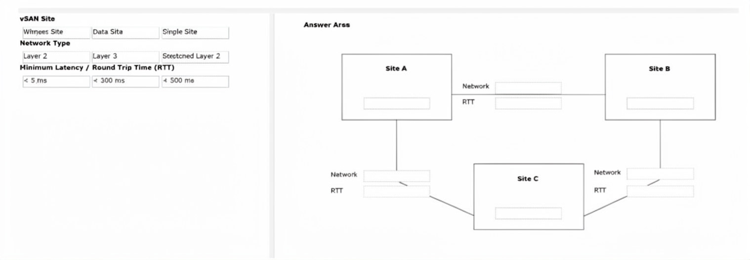
Explanation:
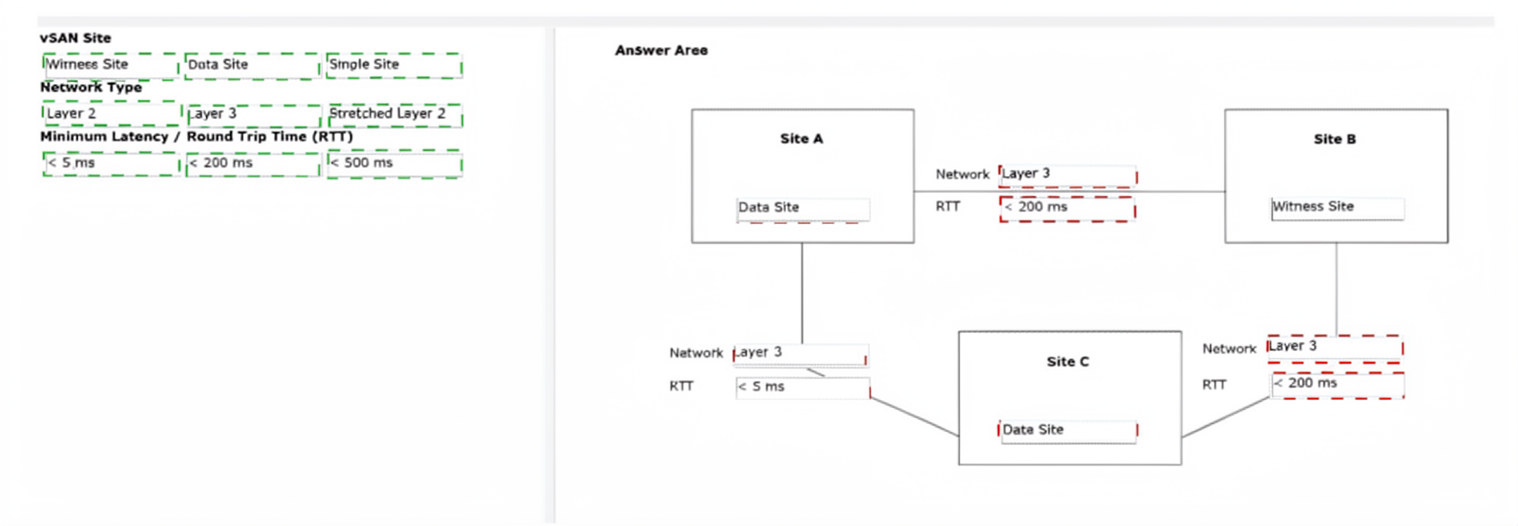
The question requires configuring a vSAN Stretched Cluster across three sites using 10 new ESXi hosts while minimizing STP issues. Site A hosts production workloads and Site C provides capacity, making them the two data sites. Site B, at capacity with no room for hosts, is ideal for the Witness.
✅ Correct Options:
Site A → Data Site (with hosts), Network Type: Layer 3, RTT: < 5 ms (to Site C)
Site A and Site C serve as the two data sites hosting the ESXi hosts. Layer 3 networking between them with < 5 ms RTT supports synchronous replication for the stretched cluster.
Site B → Witness Site, Network Type: Layer 3, RTT: < 200 ms (to both Site A and Site C)
Site B hosts only the Witness appliance (lightweight). Layer 3 with < 200 ms RTT to each data site meets witness communication requirements.
Site C → Data Site (with hosts), Network Type: Layer 3, RTT: < 5 ms (to Site A), < 200 ms (to Site B)
Site C acts as the second data site with multiple hosts for capacity and future growth. Layer 3 networking avoids STP issues.
❌ Incorrect options:
(These would violate stretched cluster rules or site roles.)
Placing Witness at Site A or C, using Layer 2 between data sites, or exceeding latency limits (e.g., >5 ms between data sites) would fail deployment or performance requirements.
🔧 Reference:
→ vSAN Stretched Cluster Design Considerations
Details data site RTT < 5 ms and witness RTT < 200 ms.
→ vSAN Stretched Cluster Networking
Recommends Layer 3 to minimize STP impact.
| Page 1 out of 7 Pages |
| 123 |
Real-World Scenario Mastery: Our 3V0-23.25 practice exam don't just test definitions. They present you with the same complex, scenario-based problems you'll encounter on the actual exam.
Strategic Weakness Identification: Each practice session reveals exactly where you stand. Discover which domains need more attention, before Advanced VMware Cloud Foundation 9.0 Storage exam day arrives.
Confidence Through Familiarity: There's no substitute for knowing what to expect. When you've worked through our comprehensive 3V0-23.25 practice exam questions pool covering all topics, the real exam feels like just another practice session.
Copyright © All Rights Reserved