Topic 1, Exam Pool A
Which two statements about VRF-Lite configurations are true? (Choose two.)
A.
They support the exchange of MPLS labels
B.
Different customers can have overlapping IP addresses on different VPNs
C.
They support a maximum of 512.000 routes
D.
Each customer has its own dedicated TCAM resources
E.
Each customer has its own private routing table
F.
They support IS-IS
Different customers can have overlapping IP addresses on different VPNs
Each customer has its own private routing table
Summary
VRF-Lite is a simplified form of MPLS VPNs that provides network virtualization by creating multiple virtual routing and forwarding instances on a single physical router. It allows for complete separation of routing information for different customers or purposes without requiring the full MPLS protocol suite in the core. This makes it ideal for enterprise networks or as a edge technology where full MPLS is not deployed.
Correct Options
B. Different customers can have overlapping IP addresses on different VPNs
This is a fundamental capability and primary benefit of VRF-Lite. By creating separate routing instances (VRFs), the IP forwarding tables are logically segregated.
An IP address like 10.1.1.0/24 can exist in VRF_Customer_A and also in VRF_Customer_B without any conflict, as each VRF is its own isolated routing domain.
This allows service providers or enterprises to host multiple customers or departments using private IP address space without requiring coordination.
E. Each customer has its own private routing table
The core component of a VRF is a separate IP routing table. Each VRF instance maintains its own unique routing table, which includes its own set of routes, interfaces, and routing protocol processes.
This private routing table ensures that traffic and routing information from one VRF are completely isolated from all other VRFs on the same physical router.
This isolation is what enables the overlapping IP address capability mentioned in option B.
Incorrect Options
A. They support the exchange of MPLS labels
This is false. VRF-Lite is defined by the absence of MPLS. It uses standard IP forwarding within each VRF. While a router configured with VRF-Lite can be connected to an MPLS cloud, the VRF-Lite segment itself does not use or exchange MPLS labels.
C. They support a maximum of 512.000 routes
This is a specific, numerical limit that is platform and software-dependent, not a universal characteristic of VRF-Lite technology. The maximum number of routes varies significantly between router models and is not a defining "true statement" about the technology itself.
D. Each customer has its own dedicated TCAM resources
This is incorrect. While each VRF has its own logical routing table, hardware forwarding resources like TCAM (Ternary Content-Addressable Memory) are typically a shared physical resource on the router. The router's hardware enforces the VRF separation, but the TCAM itself is not physically partitioned per VRF.
F. They support IS-IS
Standard VRF-Lite supports IPv4 unicast routing protocols like OSPF, EIGRP, and BGP. IS-IS is generally not supported within a VRF context on most Cisco platforms; it typically runs only in the global routing table.
Reference
Cisco Official Website: Configuring VRF-Lite - This documentation outlines the basic configuration and concepts, emphasizing the creation of separate routing tables for network virtualization without MPLS.
A network engineer is investigating a flapping (up/down) interface issue on a core switch that is synchronized to an NTP server. Log output currently does not show the time of the flap. Which command allows the logging on the switch to show the time of the flap according to the clock on the device?
A.
service timestamps log uptime
B.
clock summer-time mst recurring 2 Sunday mar 2:00 1 Sunday nov 2:00
C.
service timestamps log datetime localtime show-timezone
D.
clock calendar-valid
service timestamps log datetime localtime show-timezone
Summary
When troubleshooting intermittent issues like a flapping interface, precise timestamps are critical for correlating events with other system logs or network monitoring data. By default, Cisco devices may log messages with only the time since boot (uptime), which is not useful for historical analysis. To see the actual date and time of an event (synchronized via NTP), the device must be configured to tag log messages with the current calendar time and timezone, making the logs human-readable and actionable.
Correct Option
C. service timestamps log datetime localtime show-timezone
This command configures the system to timestamp log messages with the current date and time, using the device's local time setting.
The datetime keyword specifies the use of the calendar time instead of uptime.
The localtime keyword ensures the time is displayed in the configured local timezone.
The show-timezone option appends the timezone abbreviation (e.g., PST, EST) to the timestamp, which is essential for accurately interpreting logs, especially if the NTP server is in a different timezone.
Incorrect Options
A. service timestamps log uptime
This is the default behavior or a command that explicitly sets timestamps to show the time since the device was last rebooted. This is not useful for determining the absolute time an interface flap occurred and is the problem the engineer needs to solve.
B. clock summer-time mst recurring 2 Sunday mar 2:00 1 Sunday nov 2:00
This command configures the device's timezone settings for Daylight Saving Time (MST/MDT). While this is a necessary prerequisite for having the correct local time, it does not, by itself, instruct the system to apply this time to log messages. The service timestamps command is still required.
D. clock calendar-valid
This command is used on older Cisco routers to indicate that the device's internal hardware clock is reliable and can be used as a time source. It is related to timekeeping but does not control how timestamps are formatted in log messages.
Reference
Cisco Official Website: service timestamps - This documentation explains the service timestamps command and its parameters for setting the format of debug and log message timestamps.
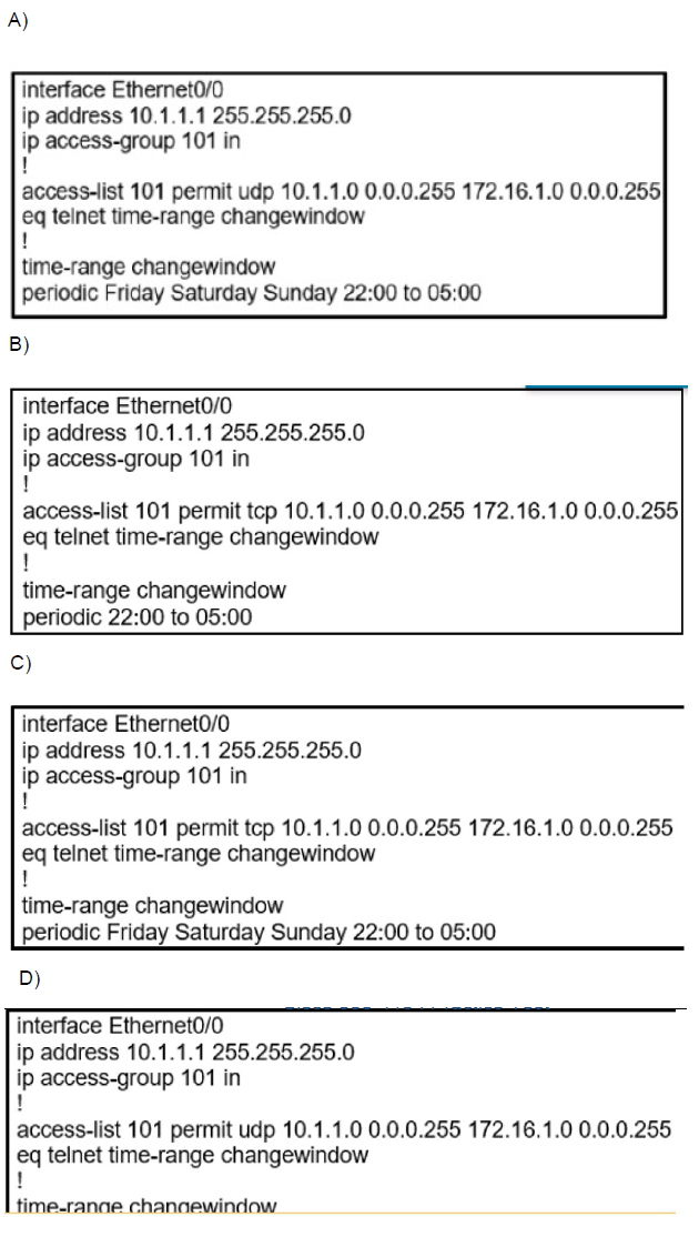
During the maintenance window an administrator accidentally deleted the Telnet-related configuration that permits a Telnet connection from the inside network (Eth0/0) to the outside of the networking between Friday – Sunday night hours only. Which configuration resolves the issue?
A.
Option A
B.
Option B
C.
Option C
D.
Option D
Option C
Summary:
This question involves recovering a time-based ACL configuration that originally permitted Telnet access from the internal network (10.1.1.0/24 on Ethernet0/0) to an external host (172.16.1.0/24) only during Friday to Sunday, 22:00 to 05:00. The deletion requires restoring the correct protocol (TCP port 23 for Telnet) and periodic time-range in the access-list to enable inbound connections during the maintenance window without affecting other traffic.
Correct Option:
C.
Option C correctly uses "permit tcp" to match Telnet's TCP protocol on port 23, essential for allowing inbound Telnet sessions from the external host.
The time-range "changewindow" with "periodic Friday Saturday Sunday 22:00 to 05:00" precisely restores the weekend night hours for maintenance access.
Applying "ip access-group 101 in" on Ethernet0/0 ensures the ACL filters inbound traffic, permitting the specified Telnet connections while blocking others outside the time window.
Incorrect Option:
A.
Uses "permit udp" instead of TCP, which mismatches Telnet's protocol, preventing actual Telnet sessions despite correct source/destination and time-range.
While the periodic days and hours are accurate, the protocol error renders the ACL ineffective for Telnet recovery.
Incorrect Option:
B.
Specifies "permit tcp" correctly but omits the "eq telnet" (or eq 23) operator after the source, failing to identify Telnet traffic specifically.
Lacks the periodic days (Friday Saturday Sunday), limiting the range to unspecified times, which does not align with the required weekend maintenance window.
Incorrect Option:
D.
Applies the time-range "changewindow" directly in the ACL line without "eq", causing a syntax error and preventing proper configuration.
Although using UDP is incorrect for Telnet, the primary issue is the malformed time-range reference, which would not apply the periodic schedule correctly.
Reference:
Cisco IOS Security Configuration Guide: Access Control Lists, Cisco IOS Release 15M&T - Time-Based Access Control Lists
Refer to the exhibit.
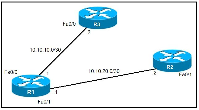
An IP SLA was configured on router R1 that allows the default route to be modified in the event that Fa0/0 loses reachability with the router R3 Fa0/0 interface. The route has changed to flow through router R2. Which debug command is used to troubleshoot this issue?
A.
debug ip flow
B.
debug ip sla error
C.
debug ip routing
D.
debug ip packet
debug ip routing
Summary
The scenario describes an IP SLA tracking configuration used for Object Tracking and Policy-Based Routing (PBR) or Floating Static Routes. When the IP SLA operation fails (due to loss of reachability to R3's Fa0/0), it triggers a change in the routing table, removing the primary default route via R3 and installing a secondary (floating) default route via R2. To observe the dynamic changes in the routing table as they happen in real-time, you need to debug the routing process itself.
Correct Option
C. debug ip routing
This command displays any changes made to the IP routing table in real-time.
When the IP SLA operation fails, it would show the removal of the default route via R3's Fa0/0 interface.
Subsequently, it would show the installation of the floating static default route via R2's Fa0/1 interface with a higher administrative distance.
This provides direct visibility into the routing decision that is causing the traffic path to change, which is the core of the issue being investigated.
Incorrect Options
A. debug ip flow
This is not a standard Cisco IOS command. The correct command for NetFlow is debug ip flow export, which is used to troubleshoot the export of NetFlow data to a collector. It provides no information about routing table changes or IP SLA operations.
B. debug ip sla error
While this command can show errors related to the IP SLA operation's configuration or execution (e.g., inability to initiate a probe), it does not show the resulting action taken by the router. The issue described is not an IP SLA error, but the successful execution of a failover action—the route change itself. debug ip routing shows the effect of the SLA failure.
D. debug ip packet
This command shows detailed information for every IP packet processed by the router. It is extremely verbose and would generate a massive amount of output, mostly unrelated to the route change. It is used for low-level packet forwarding issues, not for observing high-level routing protocol or static route changes.
Reference
Cisco Official Website: debug ip routing - This documentation confirms the command displays routing table changes, including when routes are added, deleted, or modified.
Refer to the exhibit.

An administrator noticed that after a change was made on R1, the timestamps on the system logs did not match the clock. What is the reason for this error?
A.
An authentication error with the NTP server results in an incorrect timestamp.
B.
The keyword localtime is not defined on the timestamp service command.
C.
The NTP server is in a different time zone.
D.
The system clock is set incorrectly to summer-time hours.
The keyword localtime is not defined on the timestamp service command.
Summary
The configuration and show clock output reveal a critical mismatch. The device's clock is correctly set to Mountain Standard Time (MST), which is UTC -7, as shown by the command clock timezone MST -7 0 and the output *06:13:44.045 MST Sun Dec 30 2018. However, the log message at the bottom is timestamped *Dec 30 13:15:28, which is in UTC (as it lacks a timezone and the hour is 13, which is 7 hours ahead of 06). The service timestamps log datetime command without the localtime keyword causes the system to use UTC for log messages, creating a discrepancy with the device's local clock.
Correct Option
B. The keyword localtime is not defined on the timestamp service command.
The commands service timestamps log datetime and service timestamps debug datetime msec are configured, but they are missing the crucial localtime keyword.
Without localtime, the router defaults to using Coordinated Universal Time (UTC) for all log and debug message timestamps.
This is why the system clock shows "06:13:44 MST" (local time), but the syslog message is stamped "13:15:28" (UTC). Adding localtime to the service timestamp commands would synchronize the log timestamps with the device's configured local time.
Incorrect Options
A. An authentication error with the NTP server results in an incorrect timestamp.
There is no evidence of an NTP authentication error in the logs or the configuration. The show clock output has an asterisk (*), which indicates the clock is synchronized with an NTP source. If there were an authentication failure, the clock would not synchronize, and NTP error messages would likely appear in the logs.
C. The NTP server is in a different time zone.
The role of an NTP server is to provide the precise UTC time. It is the client's responsibility (router R1) to apply its local timezone offset to the received UTC time. The router is correctly doing this, as proven by the show clock output displaying "MST". The problem is not the timezone calculation for the clock, but the separate configuration for log timestamps.
D. The system clock is set incorrectly to summer-time hours.
The clock summer-time MST recurring command is configured, but it is inactive. The show clock output displays "MST", not "MDT" (Mountain Daylight Time), confirming that daylight saving time is not currently in effect. Therefore, the system clock is correctly set to standard time.
Reference
Cisco Official Website: service timestamps - This documentation explains the service timestamps command and explicitly states that without the localtime keyword, the timestamp is derived from UTC time.
Which protocol is used to determine the NBMA address on the other end of a tunnel when mGRE is used?
A.
NHRP
B.
IPsec
C.
MP-BGP
D.
OSPF
NHRP
Summary:
This question tests understanding of mGRE (Multipoint GRE) tunnel operation in DMVPN networks. mGRE enables a single tunnel interface to connect to multiple spokes dynamically. The protocol required to resolve and discover NBMA (Non-Broadcast Multi-Access) addresses of remote tunnel endpoints is NHRP (Next Hop Resolution Protocol), which functions like ARP for NBMA networks.
Correct Option:
A.
NHRP (Next Hop Resolution Protocol) is specifically designed for DMVPN with mGRE tunnels.
Hub routers use NHRP to maintain a database of spoke NBMA addresses; spokes send NHRP Registration packets to the hub.
When traffic needs to be forwarded to a remote spoke, NHRP Resolution Request/Reply discovers the destination spoke's NBMA address for dynamic tunnel creation.
Essential for scalable multipoint topologies without static NBMA mapping configuration.
Incorrect Option:
B.
IPsec provides encryption and security for tunnel traffic but doesn't handle NBMA address resolution.
Used as an overlay on top of mGRE/NHRP for confidentiality and integrity.
Incorrect Option:
C.
MP-BGP handles route advertisement and policy distribution, not NBMA address discovery.
Used in DMVPN for advanced routing scenarios but secondary to NHRP functionality.
Incorrect Option:
D.
OSPF is an IGP for routing within the tunnel overlay network, unaware of underlying NBMA addresses.
Requires NHRP for physical connectivity before OSPF adjacency formation.
Reference:
Cisco IOS IP Routing: DMVPN Configuration Guide - NHRP
Which protocol does MPLS use to support traffic engineering?
A.
Tag Distribution Protocol (TDP)
B.
Resource Reservation Protocol (RSVP)
C.
Border Gateway Protocol (BGP)
D.
Label Distribution Protocol (LDP)
Resource Reservation Protocol (RSVP)
Summary
MPLS Traffic Engineering (MPLS-TE) allows for explicit control over the path that traffic takes through a network, independent of the IGP's shortest path. This is crucial for optimizing resource utilization, avoiding congestion, and meeting specific performance guarantees. To establish these constrained paths, MPLS-TE requires a signaling protocol that can reserve resources and set up the Label Switched Paths (LSPs) according to the calculated constraints.
Correct Option
B. Resource Reservation Protocol (RSVP)
RSVP-TE (Resource Reservation Protocol - Traffic Engineering) is the signaling protocol used by MPLS to establish Traffic Engineering tunnels (TE-LSPs).
Unlike LDP, which simply follows the IGP's path, RSVP-TE can be directed to establish an LSP along a specific, explicit route.
It has extensions that allow it to signal and reserve bandwidth along the path, ensuring that the required resources are available to meet the Service Level Agreement (SLA).
Incorrect Options
A. Tag Distribution Protocol (TDP)
TDP was Cisco's proprietary precursor to LDP. Like LDP, it was used for basic label distribution in a non-TE MPLS environment and simply follows the IGP path. It does not have the capabilities required for traffic engineering, such as bandwidth reservation or explicit path setup.
C. Border Gateway Protocol (BGP)
BGP is primarily used as a path vector routing protocol for exchanging routing information between autonomous systems. In an MPLS context, it is mainly used for distributing VPNv4 routes in a Layer 3 VPN architecture (MP-BGP). It is not used to signal MPLS labels for traffic engineering LSPs.
D. Label Distribution Protocol (LDP)
LDP is the standard protocol for distributing labels in a basic MPLS network. Its purpose is to build LSPs that exactly follow the path chosen by the underlying IGP (the shortest path). It lacks the mechanisms for bandwidth reservation, constraint-based path calculation, and explicit routing, which are the defining features of MPLS-TE.
Reference
Cisco Official Website: MPLS Traffic Engineering Overview - This documentation confirms that "RSVP with traffic engineering extensions (RSVP-TE) is the signaling protocol that is used for MPLS TE."
Refer to the exhibit.
An engineer is trying to generate a summary route in OSPF for network 10.0.0.0/8, but the summary route does not show up in the routing table. Why is the summary route missing?
A.
The summary-address command is used only for summarizing prefixes between areas.
B.
The summary route is visible only in the OSPF database, not in the routing table.
C.
There is no route for a subnet inside 10.0.0.0/8, so the summary route is not generated
D.
The summary route is not visible on this router, but it is visible on other OSPF routers in the same area.
There is no route for a subnet inside 10.0.0.0/8, so the summary route is not generated
Summary
In OSPF, a summary route is generated only if there is at least one specific, more specific route (a component route) within the summary's address range present in the router's routing table. This is a loop-prevention mechanism. The router creating the summary must have a valid path to at least one subnet within the summarized block. If the router's routing table contains no subnets of 10.0.0.0/8 (e.g., 10.1.1.0/24, 10.2.2.0/24), then there is nothing to summarize, and the OSPF process will not advertise the summary route.
Correct Option
C. There is no route for a subnet inside 10.0.0.0/8, so the summary route is not generated
OSPF requires specific component routes to create a valid summary. The summary-address command instructs the router to advertise a summary, but the advertisement is conditional.
The router checks its OSPF database and routing table for specific routes that fall within the 10.0.0.0/8 range.
If no such specific routes exist, the summary is logically suppressed to prevent advertising a route to a network that the router itself cannot reach specifically. This prevents blackholing traffic.
Incorrect Options
A. The summary-address command is used only for summarizing prefixes between areas.
This is incorrect. The summary-address command is used on an Autonomous System Boundary Router (ASBR) to summarize external routes being redistributed into OSPF. For summarizing routes between OSPF areas, the area range command is used on an Area Border Router (ABR). The question's context is ambiguous but implies external summarization, and the principle of requiring component routes applies in both cases.
B. The summary route is visible only in the OSPF database, not in the routing table.
This is false. A successfully generated OSPF summary route is installed in the routing table of the router that creates it (the ASBR or ABR) and is then advertised to other routers. If it's not in the local routing table, it was never generated.
D. The summary route is not visible on this router, but it is visible on other OSPF routers in the same area.
This is highly unlikely. For another router to have the summary route, the summarizing router (ASBR or ABR) must have generated and advertised it. If the summarizing router does not have the route in its own table, it cannot advertise it to others. The problem originates at the source of the summarization.
Reference
Cisco Official Website: OSPF Summary Address Command - The documentation for the summary-address command implies its function is to summarize redistributed routes, and the fundamental rule of summarization in any routing protocol is the existence of component routes.
Which configuration enabled the VRF that is labeled “Inet” on FastEthernet0/0?
A.
R1(config)# ip vrf Inet
R1(config-vrf)#interface FastEthernet0/0
R1(config-if)#ip vrf forwarding Inet
B.
R1(config)#router ospf 1 vrf Inet
R1(config-router)#ip vrf forwarding FastEthernet0/0
C.
R1(config)#ip vrf Inet FastEthernet0/0
D.
R1(config)# ip vrf Inet
R1(config-vrf)#ip vrf FastEthernet0/0
R1(config)# ip vrf Inet
R1(config-vrf)#interface FastEthernet0/0
R1(config-if)#ip vrf forwarding Inet
Summary
Configuring a VRF on an interface is a two-step process. First, the VRF instance must be created globally. Second, the specific interface is associated with that VRF using the ip vrf forwarding command. This command assigns the interface to the VRF's routing table, effectively separating its traffic from the global routing table and other VRFs. All IP addresses on the interface must be reconfigured after applying this command, as it clears the interface's IP configuration.
Correct Option
A. R1(config)# ip vrf Inet
R1(config-vrf)#interface FastEthernet0/0
R1(config-if)#ip vrf forwarding Inet
ip vrf Inet: This command is entered in global configuration mode to create the VRF instance named "Inet".
interface FastEthernet0/0: This command moves the configuration context to the specific interface that needs to be associated with the VRF.
ip vrf forwarding Inet: This is the critical command applied under the interface configuration. It binds the physical interface FastEthernet0/0 to the VRF labeled "Inet".
Incorrect Options
B. R1(config)#router ospf 1 vrf Inet
R1(config-router)#ip vrf forwarding FastEthernet0/0
The first command is valid for enabling an OSPF process within a VRF. However, the second command ip vrf forwarding FastEthernet0/0 is completely invalid. The ip vrf forwarding command is an interface-level command, not a routing protocol command, and its syntax is ip vrf forwarding
C. R1(config)#ip vrf Inet FastEthernet0/0
This is not a valid Cisco IOS command. The VRF is created with the ip vrf
D. R1(config)# ip vrf Inet
R1(config-vrf)#ip vrf FastEthernet0/0
The first command is correct for creating the VRF. However, the second command ip vrf FastEthernet0/0 is invalid within VRF configuration mode. The command to assign an interface to a VRF is ip vrf forwarding, and it is executed under the interface configuration mode, not the VRF configuration mode.
Reference
Cisco Official Website: Configuring VRF-lite - This documentation outlines the steps: 1) Configure the VRF instance, and 2) Associate an Interface with a VRF using the ip vrf forwarding command.
Users were moved from the local DHCP server to the remote corporate DHCP server. After the move, none of the users were able to use the network. Which two issues will prevent this setup from working properly? (Choose two)
A.
Auto-QoS is blocking DHCP traffic.
B.
The DHCP server IP address configuration is missing locally
C.
802.1X is blocking DHCP traffic
D.
The broadcast domain is too large for proper DHCP propagation
E.
The route to the new DHCP server is missing
The DHCP server IP address configuration is missing locally
The route to the new DHCP server is missing
Summary
When relocating a DHCP server to a remote network segment, two critical factors must be addressed. First, IP connectivity must exist between the client subnet and the DHCP server. If a router separates them, the router must have a valid route to the DHCP server's network. Second, because DHCP discovery messages are broadcasts, the local router must be configured to forward these broadcasts to the specific remote DHCP server since routers do not forward broadcasts by default.
Correct Options
B. The DHCP server IP address configuration is missing locally
This refers to the configuration of the DHCP Relay Agent (the ip helper-address command) on the router interface facing the client subnet.
By default, a router will drop client DHCPDISCOVER broadcast packets. The ip helper-address
Without this local configuration on the router, the DHCP requests from users will never reach the remote server.
E. The route to the new DHCP server is missing
For the DHCP Relay Agent to function, the router must know how to reach the IP address specified in the ip helper-address command.
The router performs a routing table lookup for the DHCP server's IP address when forwarding the DHCPDISCOVER packet.
If there is no route in the routing table for the network where the DHCP server resides, the relayed packet will be dropped, and the process will fail.
Incorrect Options
A. Auto-QoS is blocking DHCP traffic
Auto-QoS is designed to prioritize certain types of traffic (like voice or video), not to block essential control plane protocols like DHCP. It is highly unlikely to be the cause of a complete, widespread DHCP failure for all users.
C. 802.1X is blocking DHCP traffic
802.1X is for port-based network access control. A key feature of 802.1X is that it typically allows DHCP traffic before a client is authenticated. This "pre-authentication" state is necessary for the client to obtain an IP address, which it might need for the authentication process itself. Therefore, 802.1X would not block initial DHCP discovery.
D. The broadcast domain is too large for proper DHCP propagation
While an excessively large broadcast domain is a network design best-practice violation, it does not prevent DHCP from working entirely. It might lead to other issues like high broadcast traffic, but DHCP would still function within that single broadcast domain. The core problem here is that the server is now in a different broadcast domain, separated by a router.
Reference
Cisco Official Website: Configuring the DHCP Relay Agent - This documentation explains the purpose and configuration of the ip helper-address command, which is the solution to the problem described.
Which two protocols can cause TCP starvation? (Choose two)
A.
TFTP
B.
SNMP
C.
SMTP
D.
HTTPS
E.
FTP
TFTP
FTP
Summary
TCP starvation is a phenomenon in a mixed TCP/UDP traffic environment where UDP traffic monopolizes bandwidth, causing TCP sessions to throttle back and perform poorly. This occurs because TCP has built-in congestion control mechanisms (like sliding windows and slow start) that cause it to reduce its transmission rate in response to packet loss. UDP, being connectionless and lacking congestion control, continues to send data at its originating rate, aggressively consuming available bandwidth and causing the packet loss that triggers TCP's back-off behavior.
Correct Options
A. TFTP
TFTP (Trivial File Transfer Protocol) is a UDP-based protocol (it uses port 69) commonly used for transferring configuration files or booting network devices.
During a large file transfer, TFTP will continuously stream UDP datagrams without any regard for network congestion.
This persistent, uncontrolled UDP traffic can consume a significant portion of the available bandwidth, inducing packet loss that severely impacts concurrent TCP sessions, leading to their "starvation."
E. FTP
FTP (File Transfer Protocol) is a TCP-based protocol, but its classic implementation uses a two-connection model: a control connection (port 21) and a separate data connection (port 20).
The data connection for the actual file transfer is typically high-volume and can be very aggressive.
While it uses TCP, a single large FTP transfer can consume so much bandwidth that it starves out other, more latency-sensitive TCP applications (like web browsing or email), effectively causing starvation among TCP flows themselves.
Incorrect Options
B. SNMP
SNMP (Simple Network Management Protocol) is primarily used for network monitoring and management. It generates very small, periodic packets (polling and traps). Its bandwidth usage is negligible and is not significant enough to cause congestion or starve other protocols like TCP.
C. SMTP
SMTP (Simple Mail Transfer Protocol) is a TCP-based protocol used for sending email. While it can transfer large attachments, email traffic is generally not persistent or high-volume enough in most networks to be a primary cause of TCP starvation, especially when compared to bulk file transfer protocols.
D. HTTPS
HTTPS is a TCP-based protocol used for secure web browsing. As a TCP protocol itself, it is subject to the same congestion control mechanisms and would be a victim of TCP starvation, not a cause of it. It would slow down if a UDP stream like VoIP or TFTP saturated the link.
Reference
Concept: TCP starvation is a well-documented network quality of service (QoS) concept. While a single source is difficult to pin down, Cisco's official QoS documentation and configuration guides frequently discuss the need to manage UDP traffic (like Voice and Video) to prevent it from starving elastic TCP traffic.
An engineer configured the wrong default gateway for the Cisco DNA Center enterprise interface during the install. Which command must the engineer run to correct the configuration?
A.
sudo maglev-config update
B.
sudo maglev install config update
C.
sudo maglev reinstall
D.
sudo update config install
sudo maglev-config update
Summary
Cisco DNA Center's configuration is managed through its underlying "maglev" platform. The maglev-config utility is the primary command-line tool for viewing and updating the appliance's network settings after the initial installation. This includes correcting misconfigured parameters like the IP address, subnet mask, DNS servers, and crucially, the default gateway for the enterprise interface. It allows for these changes without requiring a complete and disruptive reinstallation of the entire DNA Center system.
Correct Option
A. sudo maglev-config update
This is the standard, supported command for modifying the network configuration of a Cisco DNA Center appliance post-installation.
Executing this command launches an interactive text-based menu that allows the administrator to update key network parameters, including the default gateway for the Enterprise interface.
This command applies the changes dynamically, correcting the routing issue without the need for a full reinstall, which would be highly disruptive.
Incorrect Options
B. sudo maglev install config update
This is not a valid maglev command syntax. The correct command for updating configuration is maglev-config update.
C. sudo maglev reinstall
This command would initiate a complete reinstallation of the Cisco DNA Center software. This is an extremely disruptive process that wipes the existing configuration and services and is not the correct tool for making a simple network setting change like the default gateway.
D. sudo update config install
This is not a valid command in the Cisco DNA Center maglev CLI. It is a nonsensical combination of keywords and does not correspond to any known procedure for configuring the appliance.
Reference
Cisco Official Website: Change Network Settings for the Enterprise and Management Interfaces - This official installation guide confirms the procedure, stating: "To change the network settings for the Enterprise and Management interfaces, use the maglev-config update command."
| Page 1 out of 47 Pages |
| 123456789101112131415 |
Real-World Scenario Mastery: Our 300-410 practice exam don't just test definitions. They present you with the same complex, scenario-based problems you'll encounter on the actual exam.
Strategic Weakness Identification: Each practice session reveals exactly where you stand. Discover which domains need more attention, before Implementing Cisco Enterprise Advanced Routing and Services (300-410 ENARSI) exam day arrives.
Confidence Through Familiarity: There's no substitute for knowing what to expect. When you've worked through our comprehensive 300-410 practice exam questions pool covering all topics, the real exam feels like just another practice session.
Copyright © All Rights Reserved