Topic 1, Exam Pool A
What is a role of route distinguishers in an MPLS network?
A.
Route distinguishers define which prefixes are imported and exported on the edge router
B.
Route distinguishers allow multiple instances of a routing table to coexist within the edge router.
C.
Route distinguishers are used for label bindings.
D.
Route distinguishers make a unique VPNv4 address across the MPLS network
Route distinguishers make a unique VPNv4 address across the MPLS network
Summary
In an MPLS Layer 3 VPN, multiple customers (VRFs) can use the same private IP address space (e.g., 10.1.1.0/24). BGP must be able to distinguish between these overlapping prefixes. The Route Distinguisher (RD) is an 8-byte value prepended to a customer's IPv4 prefix to create a unique VPNv4 address. This process does not influence route selection or policy; its sole purpose is to ensure uniqueness in the BGP table of the Provider Edge (PE) routers, allowing them to maintain separate routing tables for different customers without IP address conflicts.
Correct Option
D. Route distinguishers make a unique VPNv4 address across the MPLS network
The primary and fundamental role of a Route Distinguisher (RD) is to transform a non-unique IPv4 prefix into a globally unique VPNv4 prefix.
It is prepended to the customer's IP prefix (e.g., 192.168.1.0/24 becomes 65000:100:192.168.1.0/24).
This uniqueness allows the BGP process on PE routers to store routes from multiple different customers, even if they use identical IPv4 address blocks, without conflict. The RD itself does not control which routes are imported into which VRF; that is the role of the Route Target (RT).
Incorrect Options
A. Route distinguishers define which prefixes are imported and exported on the edge router
This is the function of the Route Target (RT) extended community attribute. The RT is attached to the VPNv4 route and is used by importing and exporting route policies on PE routers to populate the correct VRF routing tables. The RD is solely for creating uniqueness.
B. Route distinguishers allow multiple instances of a routing table to coexist within the edge router.
This is the function of the VRF (Virtual Routing and Forwarding) instance itself. The VRF creates the separate routing and forwarding tables. The RD is a property of a VRF, used to tag the routes that originate from that VRF to make them unique in MP-BGP.
C. Route distinguishers are used for label bindings.
This is incorrect. Label bindings for MPLS forwarding are distributed by protocols like LDP (for IGP routes) or MP-BGP (for VPNv4 routes). The label itself is a separate value exchanged by these protocols and is not derived from or related to the Route Distinguisher.
Reference
Cisco Official Website: MPLS VPN Route Distinguishers and Route Targets - This documentation clarifies the distinct roles: "The RD is used to create a unique VPN-IPv4 prefix... The route target, which identifies a set of sites in the VPN, is carried in the BGP extended community attribute."
Which is statement about IPv6 inspection is true?
A.
It teams and secures bindings for stateless autoconfiguration addresses in Layer 3 neighbor tables
B.
It learns and secures bindings for stateful autoconfiguration addresses in Layer 3 neighbor tables
C.
It teams and secures bindings for stateful autoconfiguration addresses in Layer 2 neighbor tables
D.
It team and secures binding for stateless autoconfiguration addresses in Layer 2 neighbor tables.
It team and secures binding for stateless autoconfiguration addresses in Layer 2 neighbor tables.
Summary
IPv6 inspection, often implemented as part of a feature like IPv6 Snooping or RA Guard, is a security mechanism that operates at the data link layer (Layer 2). Its primary function is to prevent attacks like IPv6 address spoofing. It does this by building a binding table that maps IPv6 addresses to their corresponding MAC addresses and the switch port on which they are learned. This process is crucial for addresses configured via Stateless Address Autoconfiguration (SLAAC), where a host creates its own address using the Router Advertisement's prefix and its own MAC address.
Correct Option
D. It learns and secures bindings for stateless autoconfiguration addresses in Layer 2 neighbor tables
Stateless Autoconfiguration (SLAAC): This is the correct addressing method. SLAAC is the process where a host generates its own IPv6 address, making it vulnerable to spoofing without a security mechanism.
Layer 2 Neighbor Tables: This is the correct location. The feature builds a binding table on the switch that correlates the host's MAC address (Layer 2) with the IPv6 address it is using. This is a Layer 2 security table, distinct from the device's Layer 3 Neighbor Discovery Cache (ND cache).
The feature "learns" these bindings by inspecting traffic like NS/NA messages and "secures" them by dropping packets that do not match a valid binding in the table.
Incorrect Options
A. It learns and secures bindings for stateless autoconfiguration addresses in Layer 3 neighbor tables
This is incorrect because it specifies the Layer 3 neighbor table. The security binding table for features like IPv6 First-Hop Security (e.g., IPv6 Snooping) is a separate, secured database maintained by the switch at Layer 2. The Layer 3 neighbor table (the ND cache) on a router is a different construct and can be poisoned by malicious hosts.
B. It learns and secures bindings for stateful autoconfiguration addresses in Layer 3 neighbor tables
This is incorrect for two reasons. First, stateful autoconfiguration refers to DHCPv6, where a server assigns addresses. Spoofing is less common here as the server manages leases. Second, as in option A, the binding is secured in a Layer 2 table, not the Layer 3 neighbor table.
C. It learns and secures bindings for stateful autoconfiguration addresses in Layer 2 neighbor tables
This is incorrect because the primary focus of IPv6 inspection features is on stateless autoconfiguration (SLAAC), which is more vulnerable to spoofing. While some features can also learn from DHCPv6, the defining characteristic and primary use case are for securing SLAAC-derived addresses.
Reference
Cisco Official Website: IPv6 First-Hop Security Configuration Guide - This documentation discusses features like IPv6 Source Guard that "use the IPv6 neighbor binding table to validate the source of the traffic," and this binding table is built by inspecting Layer 2 messages to secure SLAAC addresses.
Which configuration adds an IPv4 interface to an OSPFv3 process in OSPFv3 address family configuration?
A.
Router ospf3 1 address-family ipv4
B.
Router(config-router)#ospfv3 1 ipv4 area 0
C.
Router(config-if)#ospfv3 1 ipv4 area 0
D.
Router ospfv3 1 address-family ipv4 unicast
Router(config-if)#ospfv3 1 ipv4 area 0
Summary
OSPFv3 was redesigned to be multi-protocol, separating the routing protocol operation from the network layer it serves. This is managed through the Address Family Identifier (AFI) framework. Configuration is split into two steps: first, enabling the OSPFv3 process for an address family (IPv4 or IPv6) under the global routing configuration, and second, assigning a specific interface to that OSPFv3 process and address family within the interface configuration mode.
Correct Option
C. Router(config-if)#ospfv3 1 ipv4 area 0
This is the correct command and configuration mode for adding an interface to an OSPFv3 process for the IPv4 address family.
The command is executed under the specific interface that needs to run OSPFv3.
The syntax ospfv3 1 ipv4 area 0 means: "Enable OSPFv3 process ID 1 on this interface for the IPv4 address family and assign it to area 0."
Incorrect Options
A. Router ospf3 1 address-family ipv4
This command uses the wrong process name. The correct command to enter the OSPFv3 configuration is router ospfv3 [process-id]. Furthermore, the address-family command is entered within the OSPFv3 router configuration mode, not as part of the initial command to enter it.
B. Router(config-router)#ospfv3 1 ipv4 area 0
This command is in the wrong configuration mode. The ospfv3 [process-id] [ipv4|ipv6] area [area-id] command is an interface-level command, not a router configuration mode command. It cannot be applied under (config-router)#.
D. Router ospfv3 1 address-family ipv4 unicast
This command sequence is partially correct for the first step but incomplete. router ospfv3 1 enters the OSPFv3 router configuration, and address-family ipv4 unicast enters the configuration sub-mode for the IPv4 AFI. However, this only defines the process. It does not add any interfaces to it. The critical step of applying the configuration to an interface is missing.
Reference
Cisco Official Website: OSPFv3 Address Families - This documentation explicitly states: "To enable OSPFv3 on an interface and to assign the interface to an area, use the ospfv3 command in interface configuration mode." It provides the exact syntax: ospfv3 process-id [ipv4 | ipv6] area area-id.
Which Cisco VPN technology can use multipoint tunnel, resulting in a single GRE tunnel interface on the hub, to support multiple connections from multiple spoke devices?
A.
DMVPN
B.
GETVPN
C.
Cisco Easy VPN
D.
FlexVPN
DMVPN
Summary
The key requirement in the question is a "multipoint tunnel, resulting in a single GRE tunnel interface on the hub, to support multiple connections from multiple spoke devices." This describes a hub-and-spoke topology where the hub router is not burdened with managing a separate tunnel interface for every single spoke. Instead, it uses one multipoint tunnel interface (like mGRE) to dynamically establish tunnels with all spokes. This architecture dramatically simplifies hub configuration and scalability.
Correct Option
A. DMVPN
Dynamic Multipoint VPN (DMVPN) is specifically designed to meet this requirement.
The hub router is configured with a single Multipoint GRE (mGRE) tunnel interface.
Spoke routers can be configured with either point-to-point GRE or mGRE tunnels.
Using a combination of mGRE and a routing protocol (like NHRP), spokes dynamically register with the hub and can also establish direct spoke-to-spoke tunnels on-demand, all while the hub maintains only one logical tunnel interface.
Incorrect Options
B. GETVPN
Group Encrypted Transport VPN (GETVPN) does not use traditional point-to-point or multipoint GRE tunnels. It operates in a "tunnel-less" manner, preserving the original IP headers and encrypting only the payload. It uses a group-based model for key distribution and does not involve configuring tunnel interfaces on the routers, so it does not meet the "single GRE tunnel interface" requirement.
C. Cisco Easy VPN
Cisco Easy VPN is a client-server architecture primarily used for remote access VPNs (e.g., employees connecting from home). The server (headend) does not use a single multipoint GRE interface for all clients. Instead, it uses dynamic virtual tunnel interfaces or group policies. It is not designed for the static, site-to-site hub-and-spoke topology described.
D. FlexVPN
While FlexVPN is a more modern and flexible solution that can implement a DMVPN-like topology, the specific technology historically and most directly associated with the description of using a single multipoint GRE interface on a hub for multiple spokes is DMVPN. FlexVPN is a framework that uses IKEv2 and can build various topologies, but the quintessential answer for this specific design is DMVPN.
Reference
Cisco Official Website: Dynamic Multipoint VPN (DMVPN) Design Guide - This documentation explains the DMVPN architecture, highlighting the use of multipoint GRE tunnels on the hub to support multiple spokes.
Which statement about MPLS LDP router ID is true?
A.
If not configured, the operational physical interface is chosen as the router ID even if a loopback is configured.
B.
The loopback with the highest IP address is selected as the router ID.
C.
The MPLS LDP router ID must match the IGP router ID.
D.
The force keyword changes the router ID to the specified address without causing any impact.
The loopback with the highest IP address is selected as the router ID.
Summary
The LDP Router ID is a critical 32-bit value that uniquely identifies an LSR in an MPLS network. LDP uses this ID in its messages and for label mapping. The selection process for the LDP Router ID is hierarchical and deterministic. It prefers a manually configured address. If no address is manually configured, it automatically selects the highest IP address among all operational loopback interfaces. If no loopback interfaces exist, it will select the highest IP address from any operational physical interface.
Correct Option
B. The loopback with the highest IP address is selected as the router ID.
This is the default, automatic behavior of LDP when a Router ID is not manually configured.
LDP scans all "up/up" loopback interfaces on the router.
From these, it selects the interface with the numerically highest IP address to use as its LDP Router ID.
This behavior ensures stability, as loopback interfaces are always up and not dependent on a physical link.
Incorrect Options
A. If not configured, the operational physical interface is chosen as the router ID even if a loopback is configured.
This is false. The selection process explicitly prioritizes loopback interfaces over physical interfaces. A physical interface's IP will only be chosen as the LDP Router ID if there are no operational loopback interfaces on the router.
C. The MPLS LDP router ID must match the IGP router ID.
This is not a requirement. While it is a very strong best practice for the LDP Router ID to match the IGP Router ID (typically the highest loopback), it is not enforced by the protocols. Mismatched IDs can lead to label distribution issues and broken LSPs, but the configuration itself is technically allowed.
D. The force keyword changes the router ID to the specified address without causing any impact.
This is false and dangerous. The force keyword in the mpls ldp router-id command (e.g., mpls ldp router-id loop0 force) immediately tears down all existing LDP sessions and re-establishes them with the new Router ID. This causes a temporary disruption in the MPLS forwarding plane and is absolutely not "without any impact." It should be used with caution.
Reference
Cisco Official Website: mpls ldp router-id - This documentation confirms the selection process: "If you do not configure an LDP router ID, the mpls ldp router-id command uses the following algorithm to determine the router ID: 1. The highest IP address of an operational loopback interface. 2. If no operational loopback interface exists, the highest IP address from an operational nonloopback interface."
A network engineer needs to verify IP SLA operations on an interface that shows on indication of excessive traffic. Which command should the engineer use to complete this action?
A.
show frequency
B.
show track
C.
show reachability
D.
show threshold
show track
Summary
IP SLA operations are often used to track the reachability or performance of a target. The operational state of these probes is then associated with a "tracked object." This tracked object is what other features, like static routes or Policy-Based Routing (PBR), actually reference to make a decision. To see the status of the IP SLA operation itself and whether it is succeeding or failing, you need to check the status of this tracked object, which provides a simplified, up/down view of the operation's result.
Correct Option
B. show track
The show track command displays the status of all tracked objects on the router.
It shows a list with the track number, what it is tracking (e.g., ip sla 10), and its state (Up/Down).
This provides a direct, high-level view of whether the IP SLA operation is considered successful (track state is UP) or has failed (track state is DOWN), which is the most efficient way to verify its operational status.
Incorrect Options
A. show frequency
This is not a valid Cisco IOS command for monitoring IP SLA. The frequency is a configuration parameter set within the IP SLA operation itself (frequency
C. show reachability
This is not a standard IP SLA verification command. While the goal of an IP SLA operation might be to check reachability, the correct commands to see the results are show ip sla statistics or show track.
D. show threshold
This is not a valid command. The threshold is a configured value within the IP SLA operation that defines the limits for operation success or failure. You can view the configuration with show ip sla configuration, but show threshold itself is invalid. The operational result of whether a threshold was breached is viewed in the statistics.
Reference
Cisco Official Website: show track - This documentation for the show track command confirms it is used to "Display tracked list information," which includes the state of tracked IP SLA operations.
While working with software images, an engineer observes that Cisco DNA Center cannot upload its software image directly from the device. Why is the image not uploading?
A.
The device must be resynced to Cisco DNA Center.
B.
The software image for the device is in install mode.
C.
The device has lost connectivity to Cisco DNA Center.
D.
The software image for the device is in bundle mode
The software image for the device is in install mode.
Summary
Cisco DNA Center manages device software images in two primary modes: Bundle and Install. A Bundle mode image is a single, monolithic file containing the entire IOS XE package. An Install mode image uses a smaller, golden host package to boot the device and then installs individual software component packages (RP, LC, etc.) separately. For PnP or DNA Center to successfully manage and distribute an image, it must be in Bundle mode. Install mode images are not directly supported for this automated upload and distribution process.
Correct Option
B. The software image for the device is in install mode.
Cisco DNA Center's Plug and Play (PnP) and software image management features are designed to work with monolithic bundle images.
Install mode images rely on a separate, more complex installation process that involves multiple packages and is not compatible with the direct image upload and distribution mechanism used by DNA Center.
When a device is in install mode, DNA Center cannot correctly parse or handle the image file structure, resulting in a failure to upload.
Incorrect Options
A. The device must be resynced to Cisco DNA Center.
While a sync issue could cause other problems, it is not the root cause for a failure to upload a software image directly from the device. The image mode is a fundamental prerequisite that is checked before the sync status would even be relevant for this specific operation.
C. The device has lost connectivity to Cisco DNA Center.
A connectivity loss would certainly prevent any data transfer, including an image upload. However, the question is focused on a specific technical constraint of the software image itself that prevents the upload, not a network reachability issue.
D. The software image for the device is in bundle mode.
This is the opposite of the correct answer. Bundle mode is the required and supported mode for software images to be uploaded and managed by Cisco DNA Center. If the image were in bundle mode, the upload should proceed without this specific issue.
Reference
Cisco Official Website: Cisco DNA Center - Software Image Management - The official documentation for device onboarding and software management specifies the requirements for software images, implicitly favoring the use of bundle images for automated provisioning and distribution, which is the standard for network management systems.
Which attribute eliminates LFAs that belong to protected paths in situations where links in a network are connected through a common fiber?
A.
shared risk link group-disjoint
B.
linecard-disjoint
C.
lowest-repair-path-metric
D.
interface-disjoint
shared risk link group-disjoint
Summary
In modern networks, multiple physical links often share a common underlying physical resource, such as a single fiber conduit or a shared amplifier. This creates a Shared Risk Link Group (SRLG). If two links are in the same SRLG, a single physical failure (like a backhoe cutting a fiber conduit) can cause both links to fail simultaneously. A Loop-Free Alternate (LFA) path that uses a link within the same SRLG as the protected link is not a valid backup, as it would likely fail at the same time. Therefore, the LFA calculation must be constrained to eliminate such candidates.
Correct Option
A. shared risk link group-disjoint
This attribute explicitly instructs the IP Fast Reroute (IP FRR) calculation to exclude any candidate LFA paths that traverse a link sharing a common SRLG with the primary protected link.
It ensures that the backup path is physically diverse from the primary path at the infrastructure level (e.g., different fiber conduits).
This provides a much higher level of resiliency against common-cause failures, which is critical in optical networks.
Incorrect Options
B. linecard-disjoint
This attribute ensures the LFA path does not use an interface located on the same line card as the primary protected interface. It protects against a line card failure but does not protect against a shared physical infrastructure failure like a common fiber, which is the specific scenario described.
C. lowest-repair-path-metric
This is not a standard LFA attribute. The standard LFA calculation already prefers the path with the lowest metric to the destination. This option seems to be a distractor describing the default behavior, not a constraint for eliminating paths based on shared risk.
D. interface-disjoint
This is a weaker form of disjointedness. It simply ensures the LFA does not use the same physical interface as the primary path. It does not guarantee that the LFA's physical path is diverse from the primary path's physical path (e.g., two different interfaces on the same router could still be in the same fiber bundle).
Reference
Cisco Official Website: IP Fast Reroute Loop-Free Alternate Shared Risk Link Groups - This documentation explains the purpose of SRLG and how to configure OSPF to "compute a loop-free alternate (LFA) that does not use any link that is a member of a shared risk link group (SRLG) of the protected link."
Which protocol is used in a DMVPN network to map physical IP addresses to logical IP addresses?
A.
BGP
B.
LLDP
C.
EIGRP
D.
NHRP
NHRP
Which two statements about redistributing EIGRP into OSPF are true? (Choose two)
A.
The redistributed EIGRP routes appear as type 3 LSAs in the OSPF database
B.
The redistributed EIGRP routes appear as type 5 LSAs in the OSPF database
C.
The administrative distance of the redistributed routes is 170
D.
The redistributed EIGRP routes appear as OSPF external type 1
E.
The redistributed EIGRP routes as placed into an OSPF area whose area ID matches the EIGRP autonomous system number
F.
The redistributed EIGRP routes appear as OSPF external type 2 routes in the routing table
The redistributed EIGRP routes appear as type 5 LSAs in the OSPF database
The redistributed EIGRP routes appear as OSPF external type 2 routes in the routing table
Refer to the exhibit.
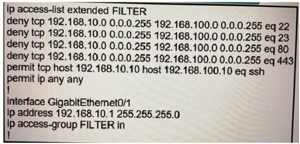
The ACL is placed on the inbound Gigabit 0/1 interface of the router. Host 192.168.10.10cannot SSH to host 192.168.100.10 even though the flow is permitted. Which action resolves the issue without opening full access to this router?
A.
Move the SSH entry to the beginning of the ACL
B.
Temporarily move the permit ip any any line to the beginning of the ACL to see if the flow works
C.
Temporarily remove the ACL from the interface to see if the flow works
D.
Run the show access-list FILTER command to view if the SSH entry has any hit statistic associated with it
Move the SSH entry to the beginning of the ACL
Refer to the exhibit.
An engineer is trying to configure local authentication on the console line, but the device is trying to authenticate using TACACS+. Which action produces the desired configuration?
A.
Add the aaa authentication login default none command to the global configuration.
B.
Replace the capital “C” with a lowercase “c” in the aaa authentication login Console local command.
C.
Add the aaa authentication login default group tacacs+ local-case command to the
global configuration.
D.
Add the login authentication Console command to the line configuration
Add the login authentication Console command to the line configuration
| Page 2 out of 47 Pages |
| 123456789101112131415 |
| 300-410 Practice Test Home |
Real-World Scenario Mastery: Our 300-410 practice exam don't just test definitions. They present you with the same complex, scenario-based problems you'll encounter on the actual exam.
Strategic Weakness Identification: Each practice session reveals exactly where you stand. Discover which domains need more attention, before Implementing Cisco Enterprise Advanced Routing and Services (300-410 ENARSI) exam day arrives.
Confidence Through Familiarity: There's no substitute for knowing what to expect. When you've worked through our comprehensive 300-410 practice exam questions pool covering all topics, the real exam feels like just another practice session.
Copyright © All Rights Reserved