Refer to the exhibit, which shows a partial troubleshooting command output.
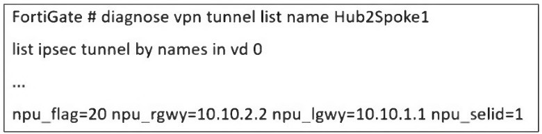
An administrator is extensively using IPsec on FortiGate. Many tunnels show information
similar to the output shown in the exhibit.
What can the administrator conclude?
A. IPsec SAs cannot be offloaded
B. The two IPsec SAs, inbound and outbound, are copied to the NPU
C. Only the outbound IPsec SA is copied to the NPU.
D. Only the inbound IPsec SA is copied to the NPU
Explanation:
The key to interpreting this output lies in the npu_flag field.
npu_flag=20:
This hexadecimal value (0x20) is a bitmask that indicates the state of the IPsec Security Associations (SAs) relative to the Network Processing Unit (NPU). The value 0x20 specifically means that the tunnel is NPU accelerated.
npu_gwy=10.10.2.2: This shows the IP address of the peer gateway as known to the NPU.
npu_lgwy=10.10.1.1: This shows the IP address of the local gateway as known to the NPU.
When an IPsec tunnel is established, two unidirectional SAs are created: one for inbound traffic and one for outbound traffic. For the tunnel to be fully accelerated by the NPU, both SAs must be successfully offloaded.
The presence of the npu_flag=0x20 and the specific NPU gateway addresses confirms that this offloading process has been successful for both SAs. The NPU now has the necessary information to encrypt and decrypt traffic for this tunnel at hardware speed, bypassing the main CPU.
Why the other options are incorrect:
A. IPsec SAs cannot be offloaded:
This is the direct opposite of what the output shows. The npu_flag being set to 0x20 is explicit proof that offloading has occurred.
C. Only the outbound IPsec SA is copied to the NPU:
For a tunnel to be functional and accelerated, both SAs must be offloaded. A partial offload would not result in the npu_flag=0x20 status, and tunnel performance would be suboptimal.
D. Only the inbound IPsec SA is copied to the NPU:
Similarly, this is incorrect. The NPU needs both the encryption (outbound) and decryption (inbound) keys and parameters to handle the full flow of traffic. The output indicates the tunnel is fully accelerated.
Reference
Fortinet Documentation:
The FortiOS CLI Reference guide for diagnose vpn tunnel commands explains the meaning of the various output fields.
Troubleshooting Guide:
Knowledge Base articles and troubleshooting guides on Fortinet's support website frequently reference npu_flag=0x20 as the indicator for a successfully NPU-offloaded IPsec tunnel. A value of npu_flag=0x00 would indicate that the tunnel is running in CPU mode, which is not the case here.
Refer to the exhibit, which shows a hub and spokes deployment.
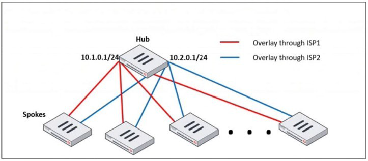
An administrator is deploying several spokes, including the BGP configuration for the
spokes to connect to the hub.
Which two commands allow the administrator to minimize the configuration? (Choose two.)
A. A. neighbor-group
B. B. route-reflector-client
C. C. neighbor-range
D. D. ibgp-enforce-multihop
Explanation:
In a large-scale hub-and-spoke VPN deployment (like the one shown with SD-WAN or IPsec overlays), the hub FortiGate can have a very large number of BGP peers (the spokes). Manually configuring each spoke as an individual BGP neighbor is time-consuming, error-prone, and difficult to scale.
The two commands provided are BGP features designed specifically to minimize configuration in such scenarios:
A. neighbor-group:
This command is used to create a template for BGP neighbor configuration. Instead of applying the same set of parameters (e.g., remote-as, password, soft-reconfiguration, timers) to dozens of individual neighbor statements, you define them once in a neighbor-group. You then simply assign each spoke neighbor to this group.
How it minimizes configuration: It centralizes and standardizes the common configuration for all spokes, drastically reducing the number of configuration lines and making future changes much easier (you change the group once instead of changing every single neighbor).
C. neighbor-range:
This command allows you to define a subnet or range of IP addresses from which the hub FortiGate will accept BGP peerings. In a dynamic spoke environment where spokes get their overlay IP addresses from a specific pool (e.g., 10.1.0.0/24 and 10.2.0.0/24), you can configure the hub to peer with any IP in that range.
How it minimizes configuration: It eliminates the need for a separate, explicit neighbor
Why the other options are incorrect:
B. route-reflector-client:
This command is a crucial part of the solution for a hub-and-spoke topology, as it allows the hub to reflect routes between spokes, avoiding the need for a full mesh of iBGP peers. However, the question specifically asks for commands that "minimize the configuration." While route-reflector-client is functionally necessary, it is typically applied within the neighbor-group or to individual neighbors. It doesn't itself reduce the number of configuration lines needed to define the peers; neighbor-group and neighbor-range do that.
D. ibgp-enforce-multihop:
This command is used when an iBGP peer is not on a directly connected network. It is often required in overlay networks. Like option B, it is a functional command that might be placed inside the neighbor-group, but it does not inherently reduce the amount of configuration needed to define multiple peers.
Reference
Fortinet Documentation: The FortiOS Handbook for Routing, specifically the BGP chapter, details the use of neighbor-group and neighbor-range for simplifying configuration in large-scale deployments.
The IT department discovered during the last network migration that all zero phase selectors in phase 2 IPsec configurations impacted network operations. What are two valid approaches to prevent this during future migrations? (Choose two.)
A. A. Use routing protocols to specify allowed subnets over the tunnel.
B. B. Configure an IPsec-aggregate to create redundancy between each firewall peer.
C. C. Clearly indicate to the VPN which segments will be encrypted in the phase two selectors.
D. D. Configure an IP address on the IPsec interface of each firewall to establish unique peer
Explanation:
The core problem is the use of zero (0.0.0.0/0) phase 2 selectors. This configuration means "encrypt all traffic that passes through this tunnel interface." While simple to configure, it is a major operational risk during network migrations because any new subnet or route added to the network might unexpectedly be sent over the IPsec tunnel, causing performance issues, blackholing traffic, or breaking other network paths.
The following two approaches prevent this by explicitly defining what traffic should use the tunnel:
C. Clearly indicate to the VPN which segments will be encrypted in the phase two selectors.
This is the most direct solution. Instead of using 0.0.0.0/0, you explicitly define the specific source and destination subnets that should be encrypted by the tunnel. For example, you would configure Phase 2 with a source of 10.1.0.0/16 and a destination of 10.2.0.0/16. This ensures that only traffic between these specific networks is eligible for encryption through the tunnel. Any new subnets added to the network will not match the selector and will not be sent over the VPN, preventing the "impact on network operations."
A. Use routing protocols to specify allowed subnets over the tunnel.
This is a more dynamic and scalable approach. You run a routing protocol (like BGP or OSPF) over the IPsec tunnel interface. The phase 2 selectors can still be specific or even broad, but the key control mechanism is the routing table. Each side of the VPN only advertises the specific subnets that are meant to be reachable over the tunnel. Even if the Phase 2 selector technically allows more traffic, a router (including a FortiGate) will only send traffic over the tunnel if there is a specific route for the destination in its routing table that points to the tunnel interface. This provides precise control over what traffic is forwarded into the encrypted path.
Why the other options are incorrect:
B. Configure an IPsec-aggregate to create redundancy between each firewall peer.
An IPsec aggregate is used to combine multiple physical or logical interfaces (e.g., multiple internet links) into a single redundant IPsec tunnel. It deals with high availability and traffic load-sharing, not with controlling which source/destination subnets are encrypted. It does not solve the problem of overly broad traffic selectors.
D. Configure an IP address on the IPsec interface of each firewall to establish unique peer.
Assigning an IP address to the IPsec tunnel interface is a standard and recommended practice for several reasons (e.g., running routing protocols, diagnostics). However, simply assigning an IP address does nothing to restrict the traffic selectors. A tunnel interface with an IP address can still have a Phase 2 selector of 0.0.0.0/0. This command does not prevent the problem described.
Reference
Fortinet Documentation: The FortiOS Handbook for IPsec VPN extensively covers Phase 2 selector configuration and the use of dynamic routing over IPsec tunnels.
Best Practice: It is a universal network security best practice to use the most specific traffic selectors possible in IPsec configurations to avoid unintended consequences and to clearly define the security policy.
Refer to the exhibit, which shows the VDOM section of a FortiGate device.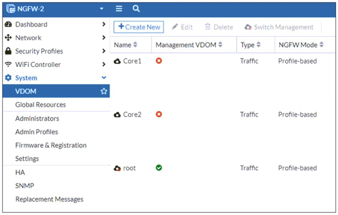
An administrator discovers that webfilter stopped working in Core1 and Core2 after a
maintenance window.
Which two reasons could explain why webfilter stopped working? (Choose two.)
A. The root VDOM does not have access to FortiManager in a closed network.
B. The root VDOM does not have a VDOM link to connect with the Corel and Core2 VDOMs.
C. The Core1 and Core2 VDOMs must also be enabled as Management VDOMs to receive FortiGuard updates
D. The root VDOM does not have access to any valid public FDN.
Explanation:
The exhibit shows a multi-VDOM environment. The key detail is that the "Management VDOM" for both Core1 and Core2 is set to root. In FortiOS, when a VDOM is in NGFW Mode (Profile-based), it relies on the Management VDOM to handle all communication with the FortiGuard Distribution Network (FDN) for services like Web Filtering, Antivirus, and IPS updates.
Let's break down why these two options are the most likely causes:
D. The root VDOM does not have access to any valid public FDN.
This is the most common cause. If the root VDOM itself cannot reach the internet (due to a missing route, failed interface, or incorrect DNS settings after maintenance), it cannot download the necessary Web Filtering databases and updates. Since Core1 and Core2 depend entirely on the root VDOM for these updates, the Web Filter service in those VDOMs will fail to function correctly. Any break in the root VDOM's internet connectivity will immediately impact all VDOMs that use it as their Management VDOM.
B. The root VDOM does not have a VDOM link to connect with the Core1 and Core2 VDOMs.
VDOM links are the internal pathways that allow VDOMs to communicate with each other. For the root VDOM to distribute FortiGuard updates to Core1 and Core2, there must be a functional VDOM link between them. A misconfiguration or removal of this link during the maintenance window would sever this critical communication channel. Even if the root VDOM has perfect internet access, the updates cannot be delivered to the core VDOMs without a VDOM link.
Why the other options are incorrect:
A. The root VDOM does not have access to FortiManager in a closed network.
While FortiManager can be used to distribute updates in offline/disconnected networks, the primary source for live updates is the public FDN. The problem statement does not mention a FortiManager or a closed network setup. The most direct and common requirement is access to the public FDN.
C. The Core1 and Core2 VDOMs must also be enabled as Management VDOMs to receive FortiGuard updates.
This is incorrect and goes against the purpose of a central Management VDOM. The whole point of designating the root VDOM as the Management VDOM for Core1 and Core2 is to avoid having to configure internet access and FortiGuard licensing in every single VDOM. Only the Management VDOM needs this access; the other VDOMs are "clients" of it.
Reference
Fortinet Documentation:
The FortiOS Administration Guide on "FortiGuard services in multi-VDOM mode" explains the requirement for the Management VDOM to have internet access and for VDOM links to be established.
CLI Verification:
To check FortiGuard connectivity from the root VDOM: execute ping update.fortiguard.net
To diagnose VDOM links and routing: get system interface (look for VDOM link interfaces) and diagnose sys vd list
Refer to the exhibit, which shows a LAN interface connected from FortiGate to two FortiSwitch devices.
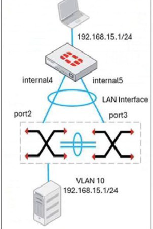
What two conclusions can you draw from the corresponding LAN interface? (Choose two.)
A. You must enable STP or RSTP on FortiGate and FortiSwitch to avoid layer 2 loopbacks.
B. The LAN interface must use a 802.3ad type interface.
C. This connection is using a FortiLInk to manage VLANs on FortiGate.
D. FortiGate is using an SD-WAN-type interface to connect to a FortiSwitch device with MCLAG.
Explanation:
The exhibit shows a single "LAN Interface" on the FortiGate connected to two separate FortiSwitch devices (internal4 and internal5). This is a classic depiction of a Multi-Chassis Link Aggregation Group (MCLAG) topology.
Let's break down why these two conclusions are correct:
B. The LAN interface must use a 802.3ad type interface.
For a switch to be part of an MCLAG, the link to the FortiGate must be a member of a Link Aggregation Group (LAG). The FortiGate presents this LAG as a single logical interface of type 802.3ad (also known as LACP). The diagram shows two physical connections from two different switches terminating into a single logical interface on the FortiGate. This is only possible if that LAN interface is an aggregate (802.3ad) interface, with port2 and port3 as its members.
C. This connection is using a FortiLink to manage VLANs on FortiGate.
"FortiLink" is the proprietary technology that allows a FortiGate to automatically discover, authorize, and manage FortiSwitch units. When a FortiGate interface is designated as a FortiLink, it becomes the management and control channel for the switches connected to it. The exhibit shows the LAN interface with a VLAN subinterface (VLAN 10) and an IP address, which is the typical setup for the FortiGate to act as the router and DHCP server for that VLAN. The FortiLink connection automatically handles the VLAN configuration and pushes it down to the managed FortiSwitches.
Why the other options are incorrect:
A. You must enable STP or RSTP on FortiGate and FortiSwitch to avoid layer 2 loopbacks.
This is not a requirement in this specific MCLAG topology. The primary purpose of MCLAG is to provide a loop-free, active-active multi-chassis link aggregation. The MCLAG peers (the two FortiSwitches) synchronize their state to prevent layer 2 loops. While STP is often enabled as a safety net, it is not the primary loop prevention mechanism here, and its absence would not cause a loop in a properly configured MCLAG.
D. FortiGate is using an SD-WAN-type interface to connect to a FortiSwitch device with MCLAG.
This is incorrect. An SD-WAN zone is used for connecting to multiple WANs (like different ISPs) for the purpose of intelligent path selection and redundancy. It is a layer 3 routing construct. The connection to FortiSwitches is a layer 2 switching and link aggregation function. The interface type used for MCLAG is 802.3ad, not SD-WAN.
Reference
Fortinet Documentation: The FortiOS Handbook for FortiSwitch integration and the FortiSwitch Guide for MCLAG configuration detail this exact setup.
The logical interface on the FortiGate is an 802.3ad aggregate.
The interface is designated as a FortiLink.
The FortiGate configures the VLAN interface on top of this FortiLink, which is then distributed to the MCLAG peer switches.
Refer to the exhibit, which shows a corporate network and a new remote office network.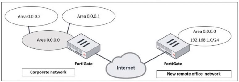
An administrator must integrate the new remote office network with the corporate
enterprise network.
What must the administrator do to allow routing between the two networks?
A. The administrator must implement BGP to inject the new remote office network into the corporate FortiGate device
B. The administrator must configure a static route to the subnet 192.168.l.0/24 on the corporate FortiGate device
C. The administrator must configure virtual links on both FortiGate devices.
D. The administrator must implement OSPF over IPsec on both FortiGate devices.
Explanation:
The exhibit depicts two distinct OSPF networks separated by the untrusted Internet. The corporate network is a multi-area OSPF domain, while the remote office is a single network. Successful integration requires a solution that accomplishes two critical tasks simultaneously:
1.Secure Connectivity:
Establishing an encrypted tunnel across the Internet to connect the two private networks.
2.Dynamic Routing:
Enabling the dynamic exchange of routing information between the two OSPF domains so each side automatically learns the other's routes.
Only option D fulfills both requirements. An IPsec VPN creates a secure, logical tunnel (often presented as a virtual tunnel interface) between the two FortiGates. Running OSPF directly over this tunnel interface allows the two devices to form an OSPF adjacency. The corporate FortiGate will then dynamically advertise the remote office's 192.168.1.0/24 network into its OSPF process, and the remote office will learn all corporate routes, creating a single, integrated routing domain.
Why the Other Options Are Incorrect
A. Implement BGP:
While BGP is a powerful WAN protocol, it is an Exterior Gateway Protocol (EGP) designed for routing between autonomous systems. It adds unnecessary complexity here. The corporate network already uses OSPF (an Interior Gateway Protocol), so extending OSPF over the VPN is the most straightforward and operationally consistent method.
B. Configure a Static Route:
A static route pointing to the remote network via the IPsec tunnel is a piece of the puzzle but is not a complete solution. It is not scalable; every new subnet at the remote office would require another manual static route. More critically, it only provides one-way communication. The remote office FortiGate would need a static route for every corporate subnet, which is completely impractical. It also does not provide a secure transport on its own.
C. Configure Virtual Links:
A virtual link is an OSPF mechanism used to connect a disconnected Area Border Router (ABR) back to the OSPF backbone (Area 0) through a non-backbone area. It is used for repairing area connectivity within a single, contiguous OSPF autonomous system. It is not a tool for connecting two separate OSPF domains across the Internet and provides no security.
Reference
Fortinet Documentation: The FortiOS Handbooks for "IPsec VPN" and "Routing" provide explicit configuration guides for this design.
The solution involves creating a route-based IPsec VPN (which generates a tunnel interface).
OSPF is then configured to run on this tunnel interface, forming a neighbor relationship and exchanging routes dynamically.
Design Principle: This "OSPF over IPsec" model is a standard and recommended design for integrating branch offices into a corporate WAN, ensuring both security and efficient, dynamic routing.
Refer to the exhibit.
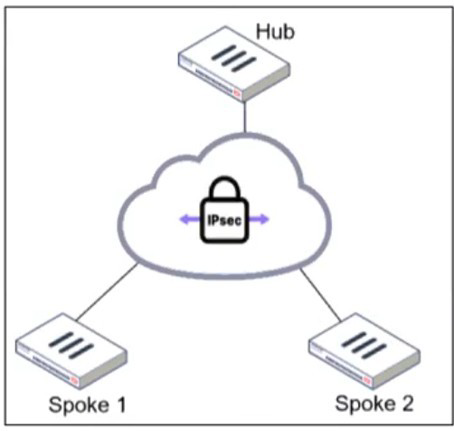
An administrator is deploying a hub and spokes network and using OSPF as dynamic protocol.
Which configuration is mandatory for neighbor adjacency?
A. Set bfd enable in the router configuration
B. Set network-type point-to-multipoint in the hub interface
C. Set rfc1583-compatible enable in the router configuration
D. Set rfc1583-compatible enable in the router configuration
Explanation:
In a hub-and-spoke IPsec VPN topology, the fundamental challenge for a link-state routing protocol like OSPF is the logical network design. While the hub is connected to multiple spokes, the spokes are not directly connected to each other; they can only communicate through the hub. This creates a logical multi-access network (like an Ethernet segment) over what is physically a set of point-to-point tunnels.
By default, OSPF treats such a multi-access network as a broadcast type. In a broadcast network, OSPF relies on a DR/BDR election process to manage the flooding of Link State Advertisements (LSAs). This process requires all routers on the segment to see each other's Hello packets to elect the DR and BDR and form adjacencies.
In a hub-and-spoke VPN, this fails because:
Spoke-to-spoke communication is typically not allowed or does not exist.
A spoke cannot see the Hello packets from other spokes.
This prevents a successful DR/BDR election, causing OSPF neighbor adjacencies to fail between the hub and the spokes.
Configuring the OSPF network-type as point-to-multipoint on the hub's tunnel interface is the mandatory correction for this scenario. This configuration:
Eliminates the DR/BDR election process entirely.
Treats the hub's connection to each spoke as an individual, logical point-to-point link.
Allows the hub to form a full OSPF adjacency directly with each spoke without requiring the spokes to see each other.
Correctly models the actual network topology, ensuring reliable and predictable routing.
Why the Other Options Are Incorrect
A. Set bfd enable in the router configuration:
Bidirectional Forwarding Detection (BFD) is a protocol used to provide rapid failure detection of the forwarding path between two routers. While it is an excellent feature for accelerating OSPF convergence in a VPN environment (highly recommended for production), it is strictly an enhancement. It is not mandatory for the initial formation of OSPF neighbor adjacencies. OSPF will form neighbors and exchange routes without BFD, albeit with slower failure detection.
C. & D. Set rfc1583-compatible enable in the router configuration:
This option is repeated and refers to a specific OSPF compatibility mode for calculating metrics for external routes (OSPF path selection for Type 1 and Type 2 external LSAs). This setting is related to the internal decision-making process of the OSPF algorithm after neighbors have already established adjacencies and exchanged routing information. It has absolutely no bearing on the underlying mechanics of neighbor discovery, Hello packet timers, or adjacency state formation, which is the core problem in a hub-and-spoke network.
Reference
Fortinet Documentation: The FortiOS Routing guide, specifically the section on OSPF configuration, addresses this exact scenario. It explicitly recommends setting the OSPF network type to point-to-multipoint on the hub interface in a hub-and-spoke VPN topology to ensure proper neighbor adjacency. This is a well-established best practice not just for FortiGate, but for OSPF implementation over VPNs in general.
Refer to the exhibit, which shows an ADVPN network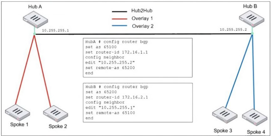
An administrator must configure an ADVPN using IBGP and EBGP to connect overlay
network 1 with 2.
What two options must the administrator configure in BGP? (Choose two.)
A. set ebgp-enforce-multrhop enable
B. set next-hop-self enable
C. set ibgp-enforce-multihop advpn
D. set attribute-unchanged next-hop
Explanation:
The topology shows two separate ADVPN networks (Overlay 1 and 2) connected via an eBGP peering between Hub A (AS 65100) and Hub B (AS 65200). The IP addresses 10.255.255.1 and 10.255.255.2 are tunnel IPs, meaning the BGP peers are not on a directly connected physical subnet.
A. ebgp-enforce-multihop enable:
This is mandatory because, by default, eBGP requires peers to be directly connected. Since the hubs communicate over a logical tunnel interface, this command is necessary to allow the eBGP session to form across this multi-hop path.
B. next-hop-self enable:
This is mandatory to ensure proper routing between the two overlay networks. When Hub A advertises a route from one of its spokes to Hub B (eBGP), the BGP NEXT_HOP attribute remains the original spoke's tunnel IP. When Hub B propagates this route to its own spokes (iBGP), the spoke in Overlay 2 sees a next-hop IP from Overlay 1, which is unreachable. Configuring next-hop-self on the hub's BGP sessions (typically on the iBGP sessions to its spokes) forces the hub to rewrite the NEXT_HOP to its own tunnel IP, which is a reachable gateway for all local spokes.
Why the Other Options Are Incorrect
C. set ibgp-enforce-multihop advpn:
This command is non-standard and unnecessary. iBGP does not have a direct-connected requirement; it can peer with any reachable IP address by default. The multihop requirement in this design is exclusively for the eBGP session between the two different autonomous systems.
D. set attribute-unchanged next-hop:
This command would break connectivity. It tells BGP to preserve the original next-hop. In this cross-overlay scenario, preserving the next-hop from one overlay in the other is the core problem, as it results in unreachable routes. Using this command would prevent the next-hop-self fix from working.
Reference
Fortinet Documentation: The FortiOS BGP configuration guide explicitly covers the need for ebgp-multihop when peering across tunnel interfaces. It also details the use of next-hop-self in hub-and-spoke VPN designs to resolve next-hop reachability issues for downstream peers. This is a fundamental BGP design pattern for this specific network topology.
An administrator must enable direct communication between multiple spokes in a
company's network. Each spoke has more than one internet connection.
The requirement is for the spokes to connect directly without passing through the hub, and
for the links to automatically switch to the best available connection.
How can this automatic detection and optimal link utilization between spokes be achieved?
A. Set up OSPF routing over static VPN tunnels between spokes
B. Utilize ADVPN 2.0 to facilitate dynamic direct tunnels and automatic link optimization.
C. Establish static VPN tunnels between spokes with predefined backup routes.
D. Implement SD-WAN policies at the hub to manage spoke link quality.
Explanation:
The requirement has three critical parts:
Direct Spoke-to-Spoke Communication: Traffic should not hairpin through the hub.
Multiple Internet Connections per Spoke: The solution must handle multiple paths.
Automatic Detection & Optimal Link Utilization: The solution must be dynamic and intelligent.
Only ADVPN 2.0 meets all these requirements. It is specifically designed for this purpose:
Dynamic Direct Tunnels: Spokes initially connect to the hub via an IPsec tunnel. When a spoke needs to send traffic to another spoke, it uses the ADVPN protocol to request a shortcut. The hub provides the necessary routing and security information, allowing the two spokes to dynamically establish a direct IPsec tunnel between themselves, bypassing the hub entirely.
Automatic Link Optimization (with Multiple Paths):
ADVPN 2.0 integrates with SD-WAN. Each spoke can have multiple internet connections in an SD-WAN zone. When initiating a direct tunnel, the spokes can use SD-WAN logic to automatically select the best-performing path (e.g., lowest latency, jitter) for that specific spoke-to-spoke tunnel. If the quality of that link degrades, the SD-WAN can seamlessly switch the tunnel to the next-best available internet connection.
Why the Other Options Are Incorrect
A. Set up OSPF routing over static VPN tunnels between spokes:
This is not scalable. It requires a full mesh of manually configured, permanent IPsec tunnels between every spoke. This creates a massive configuration burden (n*(n-1)/2 tunnels) and does not automatically optimize the path based on real-time link quality; the tunnels are static.
C. Establish static VPN tunnels between spokes with predefined backup routes:
Similar to A, this relies on a manual, full-mesh configuration. While backup routes can provide redundancy, they do not provide automatic optimal link utilization. The primary and backup paths are fixed by the administrator and cannot dynamically switch based on real-time performance metrics like latency or jitter.
D. Implement SD-WAN policies at the hub to manage spoke link quality:
This solution keeps the hub as the central traffic chokepoint. While SD-WAN at the hub can optimize the path between the spoke and the hub, it does not enable direct spoke-to-spoke communication. All inter-spoke traffic would still be forced to go through the hub, violating the primary requirement.
Reference
Fortinet Documentation: The FortiOS VPN guide has a dedicated section on ADVPN, explaining how shortcut tunnels are dynamically negotiated. The integration with SD-WAN is a key feature of ADVPN 2.0, allowing for optimal path selection for these dynamic tunnels based on real-time performance SLAs. This combination is the definitive solution for scalable, self-optimizing meshed VPN networks.
Refer to the exhibit, which shows an OSPF network.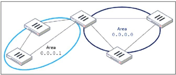
Which configuration must the administrator apply to optimize the OSPF database?
A. Set a route map in the AS boundary FortiGate.
B. Set the area 0.0.0.1 to the type STUB in the area border FortiGate.
C. Set an access list in the AS boundary FortiGate.
D. Set the area 0.0.0.1 to the type NSSA in the area border FortiGate.
Explanation:
In the topology shown, there are two OSPF areas: Area 0.0.0.0 (the backbone) and Area 0.0.0.1, which connects to it through an Area Border Router (ABR). To optimize the OSPF database, the goal is to minimize unnecessary LSAs inside Area 0.0.0.1. In typical enterprise OSPF deployments, areas that do not need to receive external routes (Type-5 LSAs) or detailed inter-area LSAs can be configured as stub areas to significantly reduce the size of the OSPF LSDB and the amount of LSA flooding.
A Stub Area replaces many external LSAs with a single default route, reducing the number of entries in the LSDB. This directly decreases CPU utilization, memory consumption, and SPF computation frequency. Since Area 0.0.0.1 is a leaf area (not redistributing external routes), it does not require Type-5 LSAs. Converting it to a stub is the simplest and most effective way to optimize the OSPF database without affecting routing reachability.
When configured as a stub, FortiGate automatically installs a default route pointing to the ABR. All external and inter-area LSAs are suppressed. Devices in Area 0.0.0.1 only maintain local routes plus the summarized default-route advertisement. This improves stability and convergence in the area by keeping LSDB contents small and controlled.
This behavior is fully aligned with OSPF design best practices: use stub areas to reduce LSDB size, optimize routing state, and reduce LSA processing overhead.
Therefore, Option B is the correct choice.
❌ Why the other options are incorrect
A. Set a route map in the AS boundary FortiGate.
Route maps are used for route redistribution, filtering, and attribute modification. They do not reduce the OSPF LSDB size inside an OSPF area. Even when filtering external routes during redistribution, Type-5 LSAs generated by other routers would still be flooded into the area unless the area is converted to a stub. Thus, using route maps does not achieve the goal of optimizing the OSPF database for the entire area.
C. Set an access list in the AS boundary FortiGate.
Access lists (ACLs) regulate packet forwarding or traffic matching, not OSPF control-plane behavior. ACLs do not influence the LSDB, do not filter LSAs, and cannot reduce LSA flooding. Therefore, ACLs are not a mechanism for OSPF optimization and provide no benefit for LSDB reduction.
D. Set the area 0.0.0.1 to the type NSSA in the area border FortiGate.
An NSSA still allows Type-7 LSAs, which are used for external route advertisements within the area. These LSAs must be generated, flooded, and translated by the ABR into Type-5 LSAs when necessary. This behavior increases LSDB size rather than reducing it. NSSA is intended for areas that must redistribute external routes—not for minimizing OSPF complexity.
Thus, NSSA does not meet the requirement of optimizing the database.
📘 References
FortiOS Routing Guide – OSPF Areas (Stub & NSSA)
FortiOS Handbook – OSPF Configuration
NSE 4 / NSE 5 Training – OSPF Area Types
Fortinet Documentation Library – OSPF Design and LSA Types
Refer to the exhibit, which shows a partial enterprise network.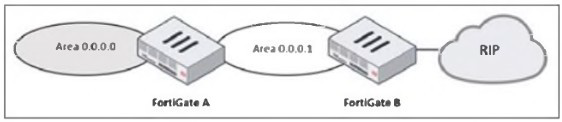
An administrator would like the area 0.0.0.0 to detect the external network.
What must the administrator configure?
A. Enable RIP redistribution on FortiGate B.
B. Configure a distribute-route-map-in on FortiGate B.
C. Configure a virtual link between FortiGate A and B.
D. Set the area 0.0.0.l type to stub on FortiGate A and B.
Explanation:
In the given topology, FortiGate B connects to a RIP network on one side and to OSPF Area 0.0.0.1 on the other. FortiGate A connects Area 0.0.0.1 to the OSPF backbone area (0.0.0.0). The administrator wants routers in the OSPF backbone to learn routes from the external RIP network. For OSPF Area 0.0.0.0 to detect external networks that originate from RIP, those RIP routes must first be imported (redistributed) into OSPF. Only then can they propagate through Area 0.0.0.1 and reach Area 0.0.0.0.
This redistribution must occur at the point where RIP and OSPF meet—FortiGate B. Without redistribution, RIP routes remain local to the RIP domain and are never introduced into the OSPF LSDB, meaning no OSPF router in Area 0.0.0.0 would ever learn them.
When the administrator enables RIP → OSPF redistribution on FortiGate B, these RIP routes are converted into Type-5 External LSAs and injected into the OSPF LSDB. These LSAs then propagate across Area 0.0.0.1, reach FortiGate A, and eventually appear in Area 0.0.0.0. This is the correct and necessary mechanism to allow OSPF to detect routes that originate outside the OSPF domain.
Redistribution is a fundamental requirement whenever two different routing protocols interoperate, which is what is happening here: RIP on one side, OSPF on the other. Therefore, option A is the only answer that ensures external detection in the OSPF backbone.
❌ Why the other options are incorrect
B. Configure a distribute-route-map-in on FortiGate B.
A distribute-route-map-in is used to filter incoming OSPF routes, not to inject external ones. It does not redistribute RIP into OSPF. Instead, it would restrict routes, which is the opposite of the intended goal. It cannot make Area 0.0.0.0 detect RIP routes.
C. Configure a virtual link between FortiGate A and B.
A virtual link is used to reconnect an OSPF area to the backbone if it becomes discontiguous. In this topology, Area 0.0.0.1 is already properly connected to Area 0.0.0.0 through FortiGate A. A virtual link does nothing to advertise or inject RIP routes. It plays no role in external route propagation.
D. Set area 0.0.0.1 to stub on FortiGate A and B.
A stub area blocks external Type-5 LSAs, which means RIP-learned routes would not propagate into Area 0.0.0.1 or Area 0.0.0.0. Making the area a stub would actively prevent external route detection. This option contradicts the goal.
📘 References
FortiOS Routing Guide → Route Redistribution (RIP ↔ OSPF)
Shows requirement for explicit redistribution between different protocols.
FortiOS Handbook – OSPF External Routes (Type-5 LSAs)
Explains how redistributed external routes are propagated.
NSE 4 & NSE 5 Training Modules → OSPF Redistribution Concepts
Recommends redistribution at the protocol boundary device.
Refer to the exhibit, which contains a partial command output.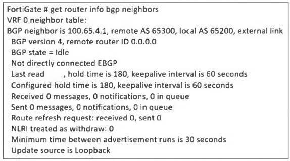
The administrator has configured BGP on FortiGate. The status of this new BGP
configuration is shown in the exhibit.
What configuration must the administrator consider next?
A. Configure a static route to 100.65.4.1.
B. Configure the local AS to 65300.
C. Contact the remote peer administrator to enable BGP
D. Enable ebgp-enforce-multihop.
Explanation:
The BGP status output shows the FortiGate’s BGP neighbor (100.65.4.1) is stuck in the Idle state. One key detail in the exhibit is the line:
“Not directly connected EBGP”
“Update source is Loopback”
This indicates the administrator has configured the update-source as a loopback interface. When BGP uses a loopback as the source, the session becomes multihop, because the loopback IP is not directly connected to the remote peer. By default, eBGP requires the neighbor to be directly connected, meaning TTL = 1. When the update source is loopback, TTL = 1 is insufficient, so the BGP session never progresses past the Idle state.
To allow an eBGP session between loopback interfaces or across intermediate hops, FortiGate requires explicitly enabling:
set ebgp-enforce-multihop enable
This command allows the FortiGate to initiate an eBGP session beyond a single hop—necessary when using loopback update sources or when the neighbors are not physically adjacent. Once this setting is applied, the FortiGate sends BGP packets with a higher TTL, allowing the session to reach the remote peer and move beyond Idle into Active/Established.
Because the exhibit clearly states the update source is loopback and that the session is “Not directly connected EBGP,” enabling multihop is the correct and required next step.
❌ Why the other options are incorrect
A. Configure a static route to 100.65.4.1.
A missing route would cause the BGP state to remain Idle, but the exhibit does not show unreachable status or missing next-hop. The key clue is the use of a loopback update source, not a reachability problem. The session would show error messages related to adjacency failure if routing was the issue. Here, the problem is TTL enforcement, not routing.
B. Configure the local AS to 65300.
The output already shows:
Remote AS 65300, Local AS 65200
These AS numbers are correct and intentional. Changing the local AS to 65300 would create an iBGP session instead of eBGP, altering routing design and not fixing the Idle state. AS mismatch is not the cause here; the cause is the loopback-based multihop requirement.
C. Contact the remote peer administrator to enable BGP.
If the remote peer had not enabled BGP, the local FortiGate would typically move to Active state (sending connection attempts). Remaining in Idle occurs before attempting TCP connection, and the "not directly connected" line indicates the problem is configuration—not a remote BGP shutdown. There is no evidence in the output that the remote router is misconfigured or unreachable.
References:
FortiOS BGP Guide → eBGP multihop configuration
FortiOS CLI Reference → set ebgp-enforce-multihop
NSE 4 / NSE 5 Routing Modules → eBGP multihop and loopback update-source behavior
FortiOS Troubleshooting BGP → Idle state diagnostics
| Page 1 out of 5 Pages |